
As an engineer specializing in hydraulic component development, I faced the challenge of creating a novel piston pump cover casting with intricate internal oil passages. This cover, essential for high-pressure hydraulic systems, demanded zero leakage and defect-free internal structures to withstand cyclic loads. Its unique design featured slender, intersecting oil channels resembling hydraulic valve bodies, combined with thick-walled sections prone to shrinkage in ductile iron (QT500-7). The casting process needed to address risks like sand core fracture, distortion, gas entrapment, and residual sand removal. Through meticulous casting process analysis, virtual simulation, and iterative design, we achieved a successful first-trial casting, validated by machining and operational testing. This article details our approach, emphasizing how virtual prototyping optimized the casting process and accelerated development.
The pump cover’s geometry, measuring 200 mm × 190 mm × 80 mm with 6-mm-thin walls and 75-mm-thick hot spots, introduced complexities in moldability and solidification control. Internal oil passages, some spanning 180 mm, required multi-piece sand cores to avoid breakage during molding, yet core assembly had to maintain precision within GB/T6414-2017-CT6 tolerances. In the casting process, the ductile iron’s tendency for shrinkage porosity in thick sections and gas defects from core emissions necessitated robust gating and feeding systems. Initial casting process feasibility studies focused on core design for easy disintegration and cleaning, pouring orientation to minimize turbulence, and strategic riser placement for directional solidification. We prioritized an integrated core assembly to reduce misalignment risks while incorporating vents to expel gases.
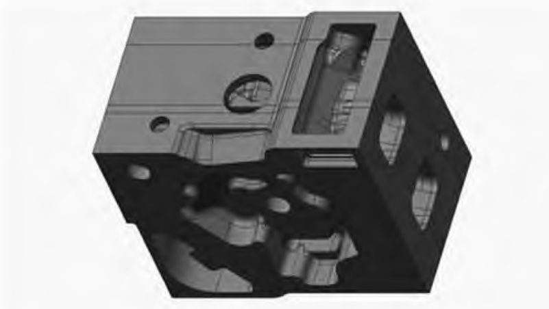
Our casting process design began with defining the pouring position. To stabilize cores and enhance mold filling, we oriented the cover’s largest face horizontally across the parting line, splitting the mold cavity equally between cope and drag. Side risers were positioned to feed thick sections directly, leveraging their thermal mass for effective feeding. The parting plane also facilitated core seating and simplified ejection, avoiding interference with machined datums. For dimensional accuracy, we applied a 0.8% shrinkage allowance to patterns and set machining allowances at 3 mm. Core design involved decomposing internal passages into six separate cores assembled via precision-located prints, limiting gaps to 0.15 mm to ensure oil-port alignment. Central vents were integrated into straight core segments to channel gases out through mold vents, preventing gas holes. The gating system used an open design with a foam ceramic filter to reduce turbulence and slag inclusion, with area ratios calculated as:
$$ F_{\text{sprue}} : F_{\text{choke}} : F_{\text{runner}} : F_{\text{gate}}} = 1.2 : 1 : 1.2 : 1.5 $$
Feeding relied on modulus calculations to position risers near hot spots, ensuring sequential solidification. The riser-to-casting modulus ratio was set at 1.5:1 to compensate for sand mold rigidity limitations:
$$ \frac{M_{\text{riser}}}{M_{\text{casting}}}} = 1.5 $$
This directed shrinkage into risers, with necks placed away from fragile cores to avoid erosion. Table 1 summarizes key casting process parameters derived from this phase.
| Parameter | Value/Ratio | Purpose in Casting Process |
|---|---|---|
| Shrinkage Allowance | 0.8% | Dimensional compensation for ductile iron solidification |
| Core Assembly Gap | ≤ 0.15 mm | Ensure oil passage precision and prevent misruns |
| Gating System Ratio | 1.2 : 1 : 1.2 : 1.5 | Minimize turbulence and inclusion entrapment |
| Modulus Ratio (Riser:Casting) | 1.5 : 1 | Enable directional solidification and feeding |
| Pouring Temperature Range | 1400°C – 1440°C | Balance fluidity with reduced gas solubility |
Virtual simulation preceded physical trials to validate the casting process. Using commercial software, we modeled fluid flow, temperature gradients, and defect formation under production conditions. The setup included resin-coated sand cores, green sand molds, and boundary conditions like a heat transfer coefficient of 500 W/(m²·K) at metal-mold interfaces. Pouring was simulated at 3.5 kg/s over 10 seconds, replicating our planned parameters. Filling analysis showed smooth metal advancement with velocities below 0.5 m/s in the cavity, eliminating core wash risks. Pressure distributions confirmed minimal turbulence, while gas entrapment maps indicated no trapped air pockets. Solidification simulations tracked thermal profiles, with liquid fraction plots confirming risers remained molten longest, enabling shrinkage compensation. Porosity predictions aligned with modulus design, showing no defects in critical zones. Simulation outcomes were pivotal in refining the casting process before tooling investment.
For physical validation, we executed the casting process on a high-pressure molding line. Cores were produced in heated die boxes, coated, and assembled into molds using clay-bonded sand. Ductile iron was melted in a medium-frequency induction furnace, treated with 0.15% inoculant during pouring at 1420°C average. Post-casting, covers were fettled, shot-blasted, and inspected. Internal passages showed no sand adherence or defects via borescope, while UT testing met Grade 2 standards. Sectioning revealed sound metal in hot spots, confirming simulation accuracy. Core assembly integrity was preserved, with all oil channels within tolerance. The first-pass success rate exceeded 96% in batch production, proving the casting process’s robustness. Table 2 compares key outcomes against initial targets, demonstrating process efficacy.
| Inspection Metric | Target | Actual Result | Role of Casting Process Control |
|---|---|---|---|
| Internal Porosity (UT) | Grade 2 | Grade 2 Achieved | Modulus-driven risering ensured feeding |
| Oil Passage Dimensional Accuracy | CT6 | Within CT6 Limits | Precision core prints minimized misalignment |
| Surface Defects in Passages | None Visible | Clean, No Adherent Sand | Core coatings and venting prevented gas/sand issues |
| Rejection Rate in Production | < 5% | < 4% | Virtual optimization reduced trial iterations |
This project underscored how systematic casting process development, anchored in simulation, mitigates risks in complex geometries. The pump cover’s demanding internal features were rendered producible through integrated core design, modulus-based feeding, and controlled filling. Virtual prototyping proved indispensable, reducing development time by forecasting defects and refining gating/risering. For similar components, early simulation should be standard in the casting process to ensure economic and technical viability. Future work will explore 3D-printed cores for enhanced passage complexity.