
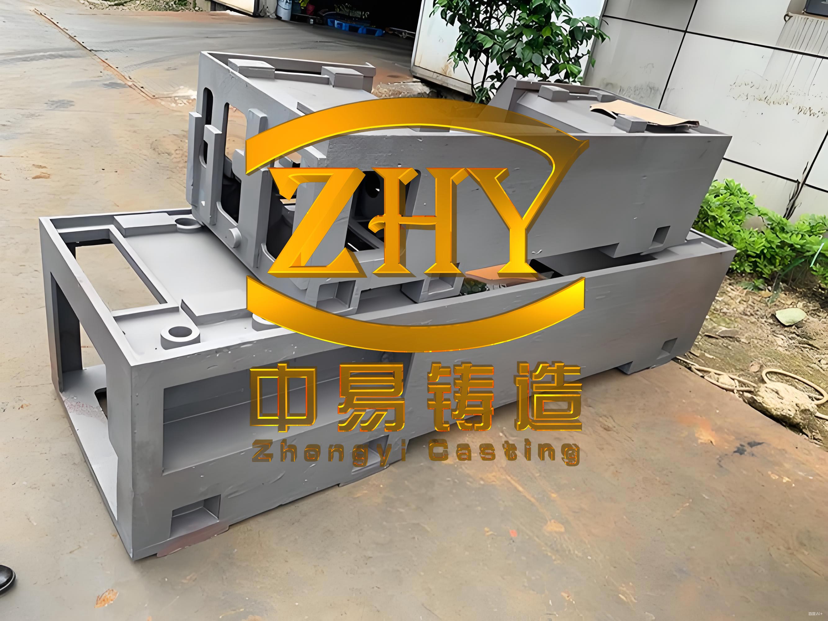
In the field of heavy industrial manufacturing, the production of large-scale machine tool castings presents significant challenges due to their complex geometries, stringent quality requirements, and the need for defect-free surfaces. As a key component in machine tools, these castings must exhibit high structural integrity, particularly on guide rails, where any imperfections like shrinkage, porosity, or cracks can compromise performance. This article details our comprehensive approach to developing a heavy machine tool column casting, focusing on innovative gating system design, effective crack prevention strategies, and precise process control. The machine tool casting in question has overall dimensions of approximately 7,120 mm in length, 2,760 mm in width, and 2,820 mm in height, with a main wall thickness of 40 mm and guide rail sections up to 160 mm thick. Made from HT300 gray iron, the casting weighs 59 tons in its rough state, necessitating meticulous planning and execution to achieve the desired metallurgical and mechanical properties.
The development of this machine tool casting began with a thorough analysis of its structural characteristics, which include a large internal cavity and reinforcing ribs that form a “回”-shaped pattern, increasing the risk of thermal stresses and cracking during solidification. To address these challenges, we employed advanced simulation tools to model the filling and solidification processes, allowing us to optimize key parameters before actual production. Our goal was to ensure that the final machine tool castings would meet all design specifications, with dense microstructure in critical areas and freedom from defects. This involved a multi-faceted strategy covering mold design, gating system configuration, melting practices, and pouring control, all tailored to the unique demands of heavy machine tool castings.
Mold Design and Process Determination
For the production of heavy machine tool castings, the mold design plays a pivotal role in determining the final quality. Given the substantial size and weight of the column casting, we opted for a pit molding approach, which provides the necessary stability and support during pouring and solidification. The mold was constructed with adequate venting channels at the bottom and periphery to facilitate gas escape, reducing the likelihood of blowholes or other gas-related defects. The pattern, designed with removable cores to minimize draft issues, allowed for efficient mold assembly and disassembly. This setup is particularly suitable for large machine tool castings, as it accommodates their dimensions while maintaining dimensional accuracy.
To manage solidification and prevent shrinkage defects, we incorporated risers and chills strategically. Two φ250 mm insulated risers were placed at the ends of the horizontal gating system to enable post-pouring feeding, while multiple φ40 mm vent risers were distributed across the casting to release trapped gases. For the guide rails, which require high hardness and wear resistance, we applied graphite blocks with a thickness of 80 mm. These chills promote directional solidification, ensuring that the rails solidify rapidly and develop a fine, dense microstructure. The use of chills is a common practice in machine tool castings to enhance surface properties and minimize shrinkage porosity in thick sections.
The core assembly for this machine tool casting consisted of 60 individual cores, with some weighing up to 1 ton each. Each core was equipped with vent pipes and nylon ropes to ensure proper gas evacuation, which is critical for avoiding defects like pinholes or mistruns. The cores were carefully positioned and secured using core prints, and the entire assembly was designed to withstand the metallostatic pressure during pouring. This attention to core design is essential for maintaining the internal geometry of machine tool castings and preventing shifts that could lead to dimensional inaccuracies.
Preventing cracks in heavy machine tool castings is a major concern, especially in structures with constrained geometries. For the column casting, we implemented several measures to mitigate cracking risks. Firstly, we increased the wall thickness at the upper end from 40 mm to 60 mm to enhance its resistance to tensile stresses. Additionally, we added reinforcing ribs measuring 140 mm in width and 45 mm in thickness around the internal cavities connected to the upper end. These ribs serve to slow down the cooling rate in critical areas, reducing thermal gradients and associated stresses, while also improving the overall fracture strength of the machine tool casting. Secondly, we extended the shakeout time, requiring that the casting cool naturally to below 180°C before mold removal. This gradual cooling prevents rapid thermal contractions that could induce cracks. Lastly, in the melting phase, we adjusted the carbon equivalent and increased the silicon-to-carbon ratio to lower residual stresses, as higher silicon content promotes graphitization, which relieves internal strains in gray iron machine tool castings.
| Parameter | Value | Purpose |
|---|---|---|
| Molding Method | Pit Molding | Provides stability for large castings |
| Riser Type | Insulated (φ250 mm) | Enables post-pouring feeding |
| Chill Material | Graphite Blocks (80 mm thick) | Promotes directional solidification in rails |
| Core Count | 60 | Forms internal cavities and structures |
| Maximum Shakeout Temperature | 180°C | Prevents cracking due to rapid cooling |
Gating System Design
The gating system for heavy machine tool castings must ensure smooth, controlled filling of the mold to avoid turbulence, slag entrapment, and temperature imbalances. Based on the principle of “high flow rate, low velocity, and clean, stable filling,” we designed a gating system that minimizes dynamic pressure and promotes uniform temperature distribution. For this column casting, we used a three-ladle pouring arrangement with a C-shaped horizontal runner surrounding the casting, which helps distribute molten metal evenly and reduces the risk of cold shuts or misruns. This configuration is particularly effective for tall, bulky machine tool castings, as it mitigates the effects of metallostatic head and ensures consistent filling across all sections.
To determine the cross-sectional areas of the gating system components, we adopted a closed-open design, which combines the benefits of slag trapping and smooth flow. The cross-sectional area ratio was established as follows:
$$ \Sigma A_{\text{inner}} : \Sigma A_{\text{sub-vertical}} : \Sigma A_{\text{horizontal-vertical}} : \Sigma A_{\text{vertical}} = 0.3 : 1.0 : 1.4 : 2.1 $$
where
$$ \Sigma A_{\text{inner}} $$ represents the total area of inner gates,
$$ \Sigma A_{\text{sub-vertical}} $$ for sub-vertical runners,
$$ \Sigma A_{\text{horizontal-vertical}} $$ for horizontal-vertical runners, and
$$ \Sigma A_{\text{vertical}} $$ for vertical runners. This ratio ensures that the flow is initially restricted at the sub-vertical runners to control velocity, then gradually opens up to fill the mold steadily.
In practice, the gating system comprised 6 vertical runners with a diameter of φ100 mm, 28 sub-vertical runners of φ40 mm, and 84 inner gates of φ40 mm. The actual cross-sectional areas were calculated using the formula for the area of a circle,
$$ A = \pi r^2 $$, where
$$ r $$ is the radius. For example, the total area of the sub-vertical runners is:
$$ \Sigma A_{\text{sub-vertical}} = 28 \times \pi \times (20 \, \text{mm})^2 = 28 \times 3.14 \times 400 \, \text{mm}^2 = 35,168 \, \text{mm}^2 = 351.68 \, \text{cm}^2 $$
Similarly, the inner gates area is:
$$ \Sigma A_{\text{inner}} = 84 \times \pi \times (20 \, \text{mm})^2 = 84 \times 3.14 \times 400 \, \text{mm}^2 = 105,504 \, \text{mm}^2 = 1,055.04 \, \text{cm}^2 $$
And the vertical runners area is:
$$ \Sigma A_{\text{vertical}} = 6 \times \pi \times (50 \, \text{mm})^2 = 6 \times 3.14 \times 2,500 \, \text{mm}^2 = 47,100 \, \text{mm}^2 = 471 \, \text{cm}^2 $$
This design facilitates a balanced flow, reducing the likelihood of defects in the machine tool castings and ensuring complete mold filling.
| Component | Quantity | Diameter (mm) | Total Cross-Sectional Area (cm²) |
|---|---|---|---|
| Vertical Runners | 6 | 100 | 471 |
| Sub-Vertical Runners | 28 | 40 | 351.68 |
| Inner Gates | 84 | 40 | 1,055.04 |
Melting Process
The melting process for heavy machine tool castings requires precise control over chemical composition and temperature to achieve the desired mechanical properties and minimize defects. We utilized two 20-ton medium-frequency induction furnaces operating simultaneously to produce a total of 70 tons of molten iron, ensuring a high melting rate and reduced holding time to prevent degradation of the melt. The ladles included one 30-ton and two 20-ton units, allowing for efficient transfer and pouring. This setup is essential for large-scale machine tool castings, as it maintains metal quality and consistency.
The target chemical composition for the HT300 gray iron was carefully selected to balance strength, castability, and stress resistance: carbon (C) content between 3.0% and 3.1%, silicon (Si) from 1.6% to 1.8%, manganese (Mn) from 1.0% to 1.1%, chromium (Cr) from 0.25% to 0.3%, and copper (Cu) from 0.5% to 0.6%. These elements contribute to the formation of pearlitic matrix and graphite flakes, enhancing the hardness and wear resistance required for machine tool castings. We employed spectroscopic analysis for rapid on-site composition checks and digital thermometers for temperature monitoring, ensuring that the melt met specifications before pouring.
Raw materials were meticulously chosen, with scrap steel accounting for at least 40% of the charge to refine the microstructure and reduce impurity levels. Additionally, the molten iron underwent high-temperature refining at 1,500°C in one of the 20-ton furnaces to achieve deoxidation, degassing, and slag removal. This step is crucial for improving the fluidity and cleanliness of the metal, which directly impacts the quality of machine tool castings by reducing inclusions and gas porosity.
| Element | Target Range (wt%) | Role in Casting Properties |
|---|---|---|
| Carbon (C) | 3.0–3.1 | Promotes graphitization, improves castability |
| Silicon (Si) | 1.6–1.8 | Enhances fluidity, reduces shrinkage |
| Manganese (Mn) | 1.0–1.1 | Increases strength and hardenability |
| Chromium (Cr) | 0.25–0.3 | Improves hardness and wear resistance |
| Copper (Cu) | 0.5–0.6 | Refines microstructure, enhances corrosion resistance |
Pouring Process Control
Pouring control is a critical phase in the production of heavy machine tool castings, as it directly influences the final integrity and surface quality. To optimize inoculation and improve the metallurgical properties of the iron, we implemented multiple inoculation stages: in the tapping spout, within the ladle using floating silicon, and instantaneously in the pouring cup. This multi-stage approach enhances graphite nucleation, resulting in a finer and more uniform structure in the machine tool castings, which is vital for achieving high strength and reduced shrinkage tendency.
We used three ladles for simultaneous pouring, with pre-pouring purification to remove slag and inclusions. Each pouring cup was equipped with a stopper, which was lifted only after the cups were filled with molten metal to prevent slag from entering the mold cavity. The pouring strategy followed a “fast-slow” sequence: initial rapid filling to avoid cold shuts, followed by a reduced flow rate as the metal approached the top surface to allow gases to escape and prevent boiling or run-outs. This method is particularly important for tall machine tool castings, where improper pouring can lead to defects like mistruns or excessive turbulence.
The pouring temperature was tightly controlled at 1,360°C ± 10°C across all three ladles, and the pouring time was maintained between 140 and 170 seconds. These parameters ensure adequate fluidity for complete mold filling while minimizing thermal shocks that could cause cracks or distortions in the machine tool castings. After the mold was filled, we continued to feed the insulated risers until the metal level stabilized, compensating for solidification shrinkage and ensuring dense, sound castings.
Throughout the process, we monitored variables such as metal temperature, flow rate, and mold conditions to adhere to the planned parameters. The successful implementation of these controls, combined with the optimized gating and mold design, resulted in machine tool castings that met all quality benchmarks, with no detectable defects in critical areas like the guide rails.
Results and Conclusion
The developed heavy machine tool casting was successfully produced and inspected, revealing a dense, homogeneous microstructure on the guide rails and an absence of shrinkage cavities, porosity, or cracks. Machining operations confirmed that the casting adhered to dimensional tolerances and surface quality requirements, validating the effectiveness of our工艺 approach. The use of computer simulations for filling and solidification provided valuable insights during the design phase, and the actual production outcomes closely matched the predicted results, demonstrating the reliability of virtual prototyping for complex machine tool castings.
In summary, the production of heavy machine tool castings demands an integrated strategy that encompasses advanced mold design, precise gating systems, controlled melting, and meticulous pouring practices. Our experience highlights the importance of crack prevention measures, such as strategic reinforcement and controlled cooling, in ensuring the structural integrity of large castings. The gating system design, with its balanced cross-sectional ratios, proved effective in achieving uniform filling and minimizing defects. Furthermore, the multi-stage inoculation and temperature control during pouring contributed to the superior quality of the final machine tool castings.
This project underscores the potential for optimizing manufacturing processes for heavy machine tool castings through a combination of empirical knowledge and modern simulation tools. Future work could focus on further refining these techniques for even larger or more complex castings, potentially incorporating real-time monitoring and adaptive control systems. The lessons learned here are applicable to a wide range of industrial machine tool castings, promoting higher efficiency and quality in the foundry industry.