
This study focuses on the manufacturing challenges of engine cylinder block-like structures in thermal power systems, specifically addressing shrinkage porosity, sand adhesion in steam channels, and dimensional stability. Through layered sand core assembly, bottom-gating systems, and optimized chilling/risering strategies, we demonstrate a production-worthy solution validated by MAGMA simulations and metallurgical testing.
1. Structural Challenges and Material Requirements
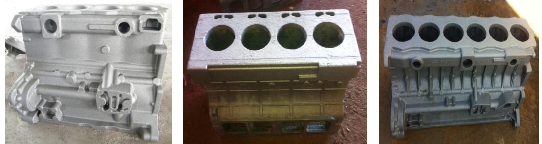
The low-pressure inner cylinder (LPIC) shares geometric complexity with engine cylinder blocks, featuring:
- Overall dimensions: 4,520 × 2,750 × 3,020 mm
- Wall thickness gradient: 40-210 mm
- Multi-layer steam channels with 3-8 mm machining allowances
Material requirements for QT400-18A equivalent:
| Property | Standard | Achieved |
|---|---|---|
| Tensile Strength (MPa) | ≥ 370 | 392 |
| Elongation (%) | ≥ 12 | 25.5 |
| Impact Energy (J) | ≥ 12 | 18-19 |
2. Solidification Control Strategy
Using Chvorinov’s rule for solidification time prediction:
$$ t = B \left( \frac{V}{A} \right)^2 $$
Where:
t = Solidification time (s)
B = Mold constant (0.8-1.2 for resin sand)
V = Section volume (m³)
A = Cooling surface area (m²)
Key process parameters for engine cylinder block-type castings:
| Parameter | Value | Rationale |
|---|---|---|
| Pouring Temperature | 1,340-1,360°C | Balances fluidity and shrinkage |
| Cooling Rate | 15-25°C/min | Avoids carbide formation |
| Feeder Efficiency | 12-18% | Compensates for liquid shrinkage |
3. Metallurgical Control System
Nodularization treatment parameters follow first-order reaction kinetics:
$$ \frac{d[Mg]}{dt} = -k[Mg] $$
Where:
[Mg] = Magnesium concentration (%)
k = Reaction rate constant (0.15-0.25 s⁻¹)
t = Treatment time (s)
Chemical composition control limits:
| Element | Base Iron | Treated Iron |
|---|---|---|
| C | 3.5-3.7% | 3.6-3.8% |
| Si | 1.4-1.8% | 2.2-2.4% |
| Mg | – | 0.035-0.050% |
4. Quality Assurance Protocol
Non-destructive testing requirements for engine cylinder block-grade castings:
$$ UT \ Sensitivity = \frac{\lambda}{2D} \sqrt{\frac{A_{defect}}{A_{beam}}} $$
Where:
λ = Ultrasonic wavelength (mm)
D = Test piece thickness (mm)
Adefect = Flaw area (mm²)
Abeam = Sound beam area (mm²)
Acceptance criteria:
- Ultrasonic Testing: Class 2-3 per ASTM A609
- Magnetic Particle: ≤ 1.6 mm indications
- Dimensional Tolerance: CT12 per ISO 8062