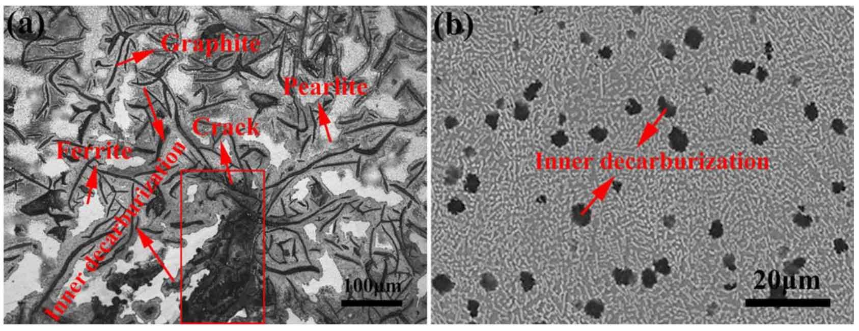
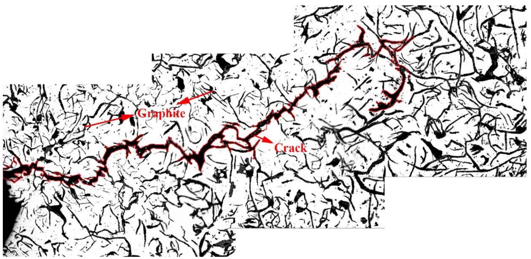
When the microcrack propagation no longer depends on the material surface conditions, the crack initiation stage ends, and the crack growth resistance depends on the overall properties of the material. We found that during the thermal cycle, due to the interaction between the sample surface and the thermal medium, on the one hand, the oxygen in the air reacts with the matrix to oxidize the surface; On the other hand, the surface matrix changes phase in the thermal medium, and a large amount of pearlite decomposes into ferrite and graphite, which reduces the hardness and strength of the material. As shown in Figure 1, due to the decomposition of cementite, the content of pearlite decreases, and the crack is easier to expand in the matrix. In gray cast iron, the existence of graphite in the matrix is an excellent bridge for crack propagation. Figure 2 shows the crack propagation morphology in the macro state and in the micro state. It can be seen from the figure that the purpose of rapid crack growth is achieved by bridging the graphite in the matrix. Therefore, the different types of graphite also make the macro thermal fatigue crack propagation different.
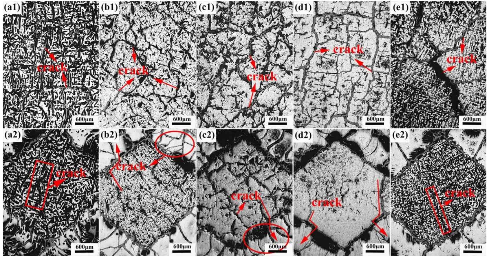
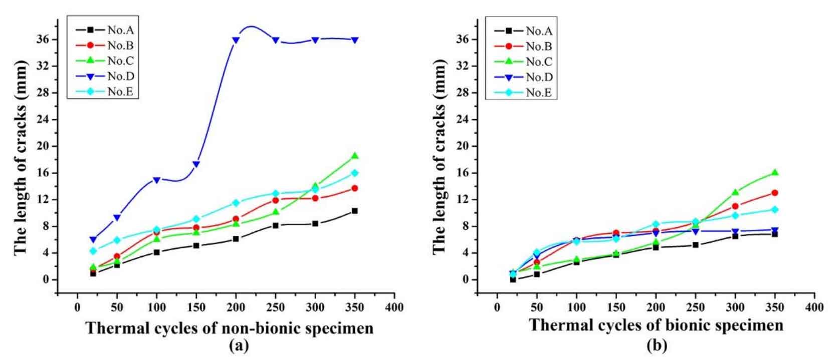
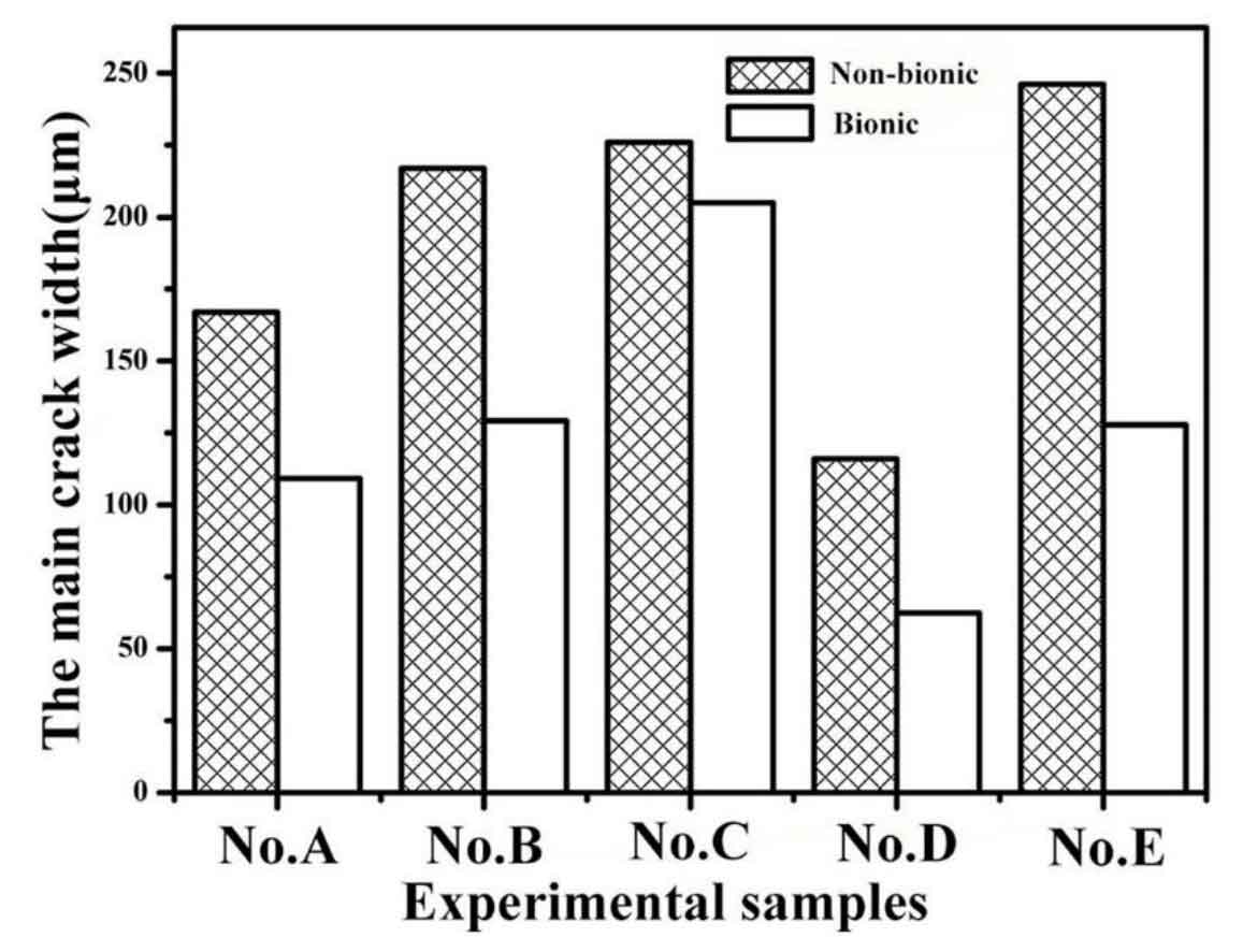
Figure 3 shows the crack morphology of non bionic surface and bionic surface of five graphite types after 350 thermal cycles. In Fig. 3 (A1), a large number of relatively independent holes are formed at the original graphite on the non bionic surface of sample No. a, while macro long cracks rarely appear. As shown in Figure 4 (a), the crack growth rate (reflected from the crack length) of sample No. A is the lowest. Therefore, the thermal fatigue resistance of all A-type graphite gray cast iron is the best. On the non bionic surface of No. B sample, the thermal fatigue crack propagation is radial, the energy required for crack propagation is dispersed in the initial stage, and the crack propagation speed is slow. In the later stage of fatigue, most of the micro cracks lose their propagation direction due to decarburization and gradually passivate, while the main crack continues to expand and branch. The coarse C-type graphite in No. C specimen has strong splitting effect and low material strength. In the later stage of thermal fatigue, taking the coarse C-type graphite as the bridge, a large number of macro cracks are formed and spread rapidly throughout the specimen. In No. D specimen, the crack rapidly expands between dendrites to form a grid crack. Fig. 4 (a) shows that after 200 thermal cycles, the crack runs through the whole specimen, and the thermal fatigue crack is the longest. However, figure 3 shows that the main crack width of sample No. D is 62.4 μ m. It can be seen that there are a large number of high-strength dendrites in No. D sample, which hinder the crack propagation, making the crack tend to expand in the dendrite gap on the surface of the sample. Therefore, D-type graphite is most likely to cause crack propagation, but the crack is shallow. No. e sample contains a large amount of directional E-type graphite. In the process of thermal cycle, small flake graphite is connected end to end, so that the main crack not only expands rapidly on the surface layer, but also easily expands inside the sample. As shown in figures 3 (E1) and 5, in the later stage of fatigue, the crack width reaches 246.2 μ m. Far more than the other four materials, it can be seen that the fatigue damage of e-type graphite is very serious. In conclusion, the crack growth rate of non bionic specimen can be expressed as No. d > No. C > No. E > No. b > No. a. In addition, the crack width of non bionic sample is No. E > No. C > No. b > No. a > No. D.