
In my extensive experience as a foundry engineer, the battle against porosity in casting is a central and ongoing challenge. Porosity in casting is not merely a cosmetic defect; it is a critical determinant of a component’s structural integrity, pressure tightness, and overall mechanical performance. It manifests as voids or holes within the solidified metal, primarily caused by entrapped air or gas during the injection process or by shrinkage during solidification. In high-pressure die casting, the rapid filling of the die cavity makes the entrapment of air the predominant source of this detrimental porosity in casting. Therefore, the core of my methodology revolves around a proactive strategy: systematic gas identification and controlled evacuation, rather than merely reacting to its symptoms in the final product.
The journey of molten metal into a sound casting is fraught with opportunities for gas entrapment. To effectively combat porosity in casting, one must first map all potential gas sources throughout the process cycle. This comprehensive understanding forms the foundation for any successful mitigation strategy.
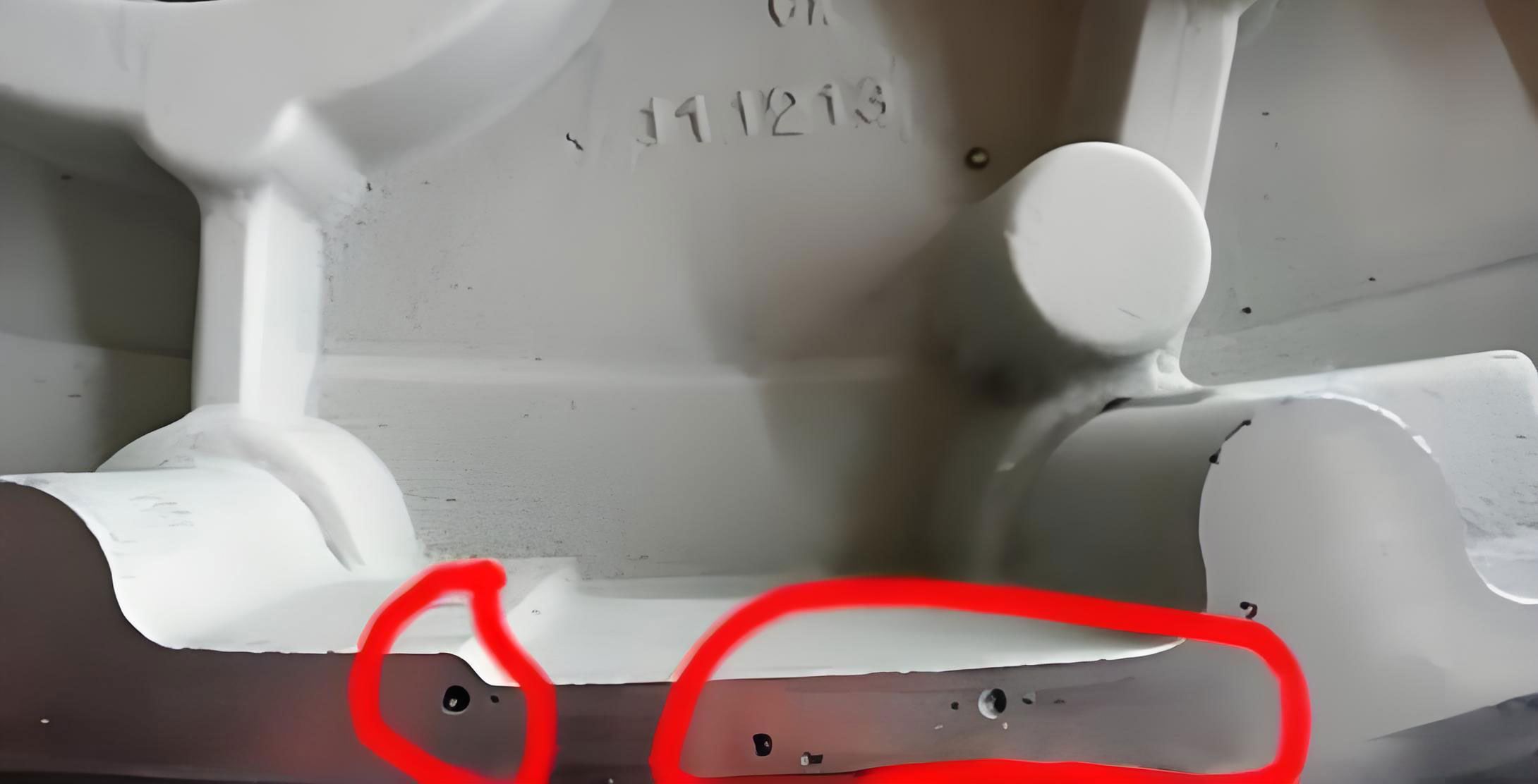
The formation of this porosity in casting, as visually suggested, is a direct consequence of failing to manage these gas sources. The figure illustrates the typical internal void structure that severely compromises part strength. My focus is on preventing such formations at their source.
Primary Sources of Gas and Porosity Formation
The gas that leads to porosity in casting originates from several key areas. A systematic breakdown is essential for targeted intervention.
| Gas Source | Description | Impact on Porosity in Casting |
|---|---|---|
| Shot Sleeve Volume | The volume of air in the horizontal shot sleeve before the plunger advances. | This is often the largest single volume of gas. If not vented ahead of the metal front, it is compressed and forced into the cavity. |
| Die Cavity & Runner System | Air occupying the empty cavity and the pathways (runners, gates) leading to it. | Gas trapped in blind pockets or last-to-fill areas directly creates porosity in casting. |
| Lubricants & Release Agents | Water- or oil-based sprays used on the plunger, shot sleeve, and die face. | If not fully vaporized (“flashed off”), the volatile components can turn to gas upon contact with molten metal, creating subsurface porosity in casting. |
| Metal Ingress | Hydrogen dissolved in the molten alloy, often from moist charge materials or humid environment. | As the metal solidifies, hydrogen solubility drops sharply, causing it to precipitate out and form fine, dispersed pinhole porosity in casting. |
The Critical Role of Shot Sleeve Venting
While venting the die cavity itself is standard practice, my experience has shown that a frequently overlooked yet massively impactful area is the shot sleeve of a horizontal cold chamber machine. Upon die closure, the volume of air contained within the shot sleeve is substantially greater than the combined volume of the cavity and runner system. If this gas is not proactively evacuated, the advancing plunger will compress it, inevitably forcing it into the die along with the metal, guaranteeing severe porosity in casting. The solution lies in intelligent venting of the shot sleeve itself.
The technique involves machining strategic vents into the shot sleeve and its housing. The primary goal is to allow the bulk of the air to escape before the molten metal reaches and seals off the venting path. This must be achieved without causing metal spillage or creating a safety hazard for the operator.
Vent System Design and Calculation
The design involves two key features machined into the stationary shot sleeve or the machine’s fixed cover:
- A Main Venting Channel: A wide, shallow groove along the top of the sleeve.
- Escape Pathways: Channels connecting this groove to the outside atmosphere through the machine housing.
The sequence of operation is crucial. As the molten alloy is ladled into the shot sleeve and the plunger begins its slow forward movement (during the first stage, or “slow shot”), the air ahead of the metal is pushed out through these vents. By the time the molten metal front rises to the top of the sleeve and reaches the vent channel, the plunger body itself should have moved forward sufficiently to block off the vent opening from the rear, preventing any metal escape. This timing is controlled by a calculated parameter: the Safety Overflow Allowance (W).
This allowance, W, is the volume of space intentionally left unfilled in the shot sleeve after ladling. It ensures that even if the ladle is slightly over-poured, the molten metal will not reach the vent before the plunger seals it. Determining the correct value for W is fundamental to eliminating this source of porosity in casting. The calculation is based on a simple volumetric balance.
Let us define the following variables:
- $m$ = Mass of the casting (including overflows and biscuit) [kg]
- $\rho$ = Density of the alloy [kg/m³]
- $D$ = Inner diameter of the shot sleeve [m]
- $L_s$ = Length of the shot sleeve (nested length) [m]
- $T_b$ = Thickness of the solidified biscuit [m]
- $W$ = Safety Overflow Allowance (the unknown we need to find) [m³]
The total volume of molten metal required ($V_{metal}$) is the sum of the casting volume and the biscuit volume:
$$V_{metal} = \frac{m}{\rho} + \frac{\pi D^2}{4} \cdot T_b$$
The available volume in the shot sleeve ($V_{sleeve}$) is:
$$V_{sleeve} = \frac{\pi D^2}{4} \cdot L_s$$
To ensure safe venting without spillage, the metal volume must be less than the sleeve volume minus the safety allowance:
$$V_{metal} \leq V_{sleeve} – W$$
Therefore, the minimum required Safety Overflow Allowance $W$ is:
$$W \geq V_{sleeve} – V_{metal}$$
$$W \geq \frac{\pi D^2}{4} \cdot L_s – \left( \frac{m}{\rho} + \frac{\pi D^2}{4} \cdot T_b \right)$$
For practical purposes and to create a universal setting for a given shot sleeve size on a machine producing various parts, $W$ is calculated based on the largest/heaviest casting planned for that machine. This conservative approach guarantees that for all smaller castings, the vent will be safely sealed by the plunger before metal reaches it, thus consistently mitigating this major source of porosity in casting. The following table summarizes this critical calculation logic.
| Variable | Symbol | Role in Preventing Porosity in Casting |
|---|---|---|
| Casting Mass | $m$ | Determines the core metal volume. Use max value for safety. |
| Shot Sleeve Diameter | $D$ | Defines the cross-sectional area for volume calculations. |
| Shot Sleeve Length | $L_s$ | Defines the total containment volume before the plunger moves. |
| Biscuit Thickness | $T_b$ | Accounts for the necessary solidified volume left in the sleeve. |
| Safety Allowance | $W$ | The calculated void that ensures vent seals before metal arrival, preventing gas entrapment and porosity in casting. |
Optimizing Die Cavity Evacuation
Even with perfect shot sleeve venting, the air within the die cavity itself must be expelled to prevent porosity in casting. This is achieved through a combination of overflow wells and ventilation channels.
- Overflows: These are small cavities connected to the last areas of the die to fill. They serve two key purposes: they act as a “trap” for cold, oxidized metal front (which often contains entrapped air), and they provide an additional pathway for air to escape. The metal flowing into the overflow helps push air out through attached vents.
- Vents: These are extremely shallow channels (typically 0.05-0.15 mm deep) machined at the die parting line or into ejector pins/cores. They are designed to allow air to escape while being shallow enough to freeze the metal almost instantly, preventing any significant leakage. Their placement is critical at the end of fill zones and around overflows. The total cross-sectional area of all vents should be carefully calculated to match the volumetric discharge rate of air during filling.
Process Parameter Synchronization
Hardware solutions alone are insufficient. The dynamic control of the injection process parameters is equally vital in the fight against porosity in casting. The modern two-stage (or multi-stage) injection profile is our primary tool.
- First Stage (Slow Shot): The plunger moves slowly to fill the shot sleeve with metal. The speed must be carefully tuned so that the metal front remains laminar and does not surge over the pour hole, trapping air. This stage lasts until the shot sleeve is about 90-95% full. A correctly executed slow shot is the first major defense against porosity in casting.
- Second Stage (Fast Shot / High Pressure): Once the metal is at the gate, the plunger accelerates rapidly to high speed to fill the cavity before the metal solidifies. This speed must be high enough to prevent misting (turbulent splashing of metal) but controlled to avoid excessive jetting that can encapsulate air. The intensification pressure is then applied to compress any remaining microscopic gas pockets and feed shrinkage.
The optimal switchover point from slow shot to fast shot is absolutely critical. If it occurs too early, air is trapped in the shot sleeve. If too late, the metal begins to solidify, leading to both cold fills and shrinkage porosity in casting. This point is often controlled by position, monitored by a linear displacement transducer on the plunger.
| Injection Phase | Key Control Parameter | Effect if Incorrectly Set | Resulting Porosity in Casting |
|---|---|---|---|
| Slow Shot | Plunger Speed (v1) | Too fast: Turbulence in sleeve. Too slow: Metal cools excessively. | Air entrapment in biscuit/sleeve; Cold shuts. |
| Transition | Switchover Position | Too early: Sleeve air forced in. Too late: Metal too cool. | Major gas pockets; Shrinkage & micro-porosity. |
| Fast Shot | Plunger Speed (v2) & Cavity Fill Time (t) | v2 too low: Misting, cold fill. v2 too high: Jetting, air entrapment. | Dispersed gas porosity; Blistering; Cold laps. |
| Intensification | Intensification Pressure (P_int) & Time | Pressure too low or time too short. | Shrinkage porosity; Gas pockets not fully compressed. |
Auxiliary Measures for Porosity Reduction
Beyond the core injection system, several supporting practices are essential for a holistic strategy against porosity in casting.
- Metal Quality and Handling: Maintaining molten metal at the correct temperature and minimizing holding time reduces gas absorption (especially hydrogen). Using dry, clean charge materials and employing degassing fluxes or rotary degassing for aluminum alloys are standard practices to reduce the hydrogen content, directly addressing one root cause of porosity in casting.
- Die Temperature Control: A stable, optimal die temperature (managed via oil heating/cooling circuits) ensures consistent fill patterns and solidification. A cold die can cause premature freezing, trapping air, while an overly hot die can lead to soldering and slower cycle times, potentially increasing gas pickup.
- Lubricant Application: Die release agents and plunger lubricants should be applied in thin, consistent coats and given adequate time to dry/ flash off before the next shot. Excessive or wet lubricant is a direct source of volatile gases that become porosity in casting.
- Vacuum-Assisted Die Casting: For the most demanding applications regarding porosity in casting (e.g., structural, heat-treatable, or leak-proof components), actively evacuating the die cavity and shot sleeve before injection is highly effective. This technology significantly reduces the amount of air present to be trapped.
Conclusion: A Systemic Approach
Minimizing porosity in casting is not about finding a single “silver bullet.” It is a systematic engineering discipline that requires attention to detail at every stage of the process. From the fundamental design of venting systems on the shot sleeve—guided by precise volumetric calculations like the Safety Allowance $W$—to the meticulous tuning of injection profiles and the disciplined control of auxiliary factors, each element plays a interconnected role.
The most persistent and damaging porosity in casting often stems from the largest initial gas volume: the shot sleeve. By prioritizing its evacuation through calculated design, we address the problem at its origin. Combining this with optimized cavity venting, synchronized process parameters, and high standards of metal and die preparation creates a robust defense. This comprehensive, first-principles approach has proven consistently effective in producing high-integrity die castings with minimized internal voids, ensuring they meet the stringent demands of modern engineering applications.