
In the production of high-temperature components for automotive and heavy machinery, Si-Mo nodular cast irons, such as QTRSi4Mo1 and QTRSiMo4.1, are indispensable for their superior high-temperature strength, oxidation resistance, and thermal stability. These characteristics make them the material of choice for demanding applications like exhaust manifolds, turbocharger housings, and other parts subjected to severe thermal cycling. However, the very alloying elements that confer these benefits—particularly high silicon and molybdenum content—significantly degrade the casting characteristics of the iron. The metal exhibits notoriously poor fluidity and a pronounced tendency towards mushy solidification, creating a persistent and costly defect in complex, thin-walled castings: shrinkage in casting.
The core of the problem lies in the solidification morphology. While standard ductile iron solidifies with a relatively well-defined skin, Si-Mo irons solidify in a mushy, pasty manner across a wide temperature range. This mode of solidification severely hinders the movement of residual liquid metal needed to compensate for the volumetric contraction that occurs as the metal changes from liquid to solid. The challenge is further magnified in exhaust manifold castings due to their inherent geometry. These components are characterized by:
- Significant variations in wall thickness.
- The presence of numerous isolated thermal masses (hot spots), such as mounting bosses, bolt pads, and flanges.
- Complex internal passageways created by intricate sand cores.
These isolated hot spots become focal points for shrinkage in casting defects, typically in the form of dispersed micro-porosity or more severe macro-shrinkage cavities, especially at the junctions (roots) of these features with the main wall. For critical areas like bolt bosses, such defects compromise mechanical integrity and sealability, leading to scrap rates that can reach 100% in severe cases. This report details our extensive investigation and the final, successful application of equilibrium solidification principles to systematically eliminate shrinkage in casting defects in Si-Mo nodular iron exhaust manifolds.
1. The Nature of the Problem: Isolated Hot Spots and Mushy Solidification
The fundamental metallurgical factors contributing to shrinkage in casting in these alloys can be summarized by their impact on key solidification parameters.
1.1 Fluid Flow and Solidification Characteristics
The poor fluidity is a direct result of high silicon content, which increases the viscosity of the molten iron and promotes the early formation of solid phases. The solidification range, the temperature interval between the liquidus and solidus, is widened. This can be conceptualized by considering the fraction of solid ($f_s$) as a function of temperature ($T$) during solidification:
$$
f_s(T) = \frac{T_L – T}{T_L – T_S}
$$
Where $T_L$ is the liquidus temperature and $T_S$ is the solidus temperature. For mushy alloys, a significant fraction of solid forms while the temperature is still relatively high, creating a coherent network that resists fluid flow. The permeability of this mushy zone is critical. Darcy’s law can be adapted to describe the flow of interdendritic liquid:
$$
\vec{v} = -\frac{K}{\mu f_l} \nabla P
$$
Here, $\vec{v}$ is the superficial velocity of the liquid, $K$ is the permeability of the mushy zone (which decreases rapidly as $f_s$ increases), $\mu$ is the dynamic viscosity, $f_l$ is the liquid fraction ($f_l = 1 – f_s$), and $\nabla P$ is the pressure gradient. In Si-Mo irons, high $f_s$ at an early stage and potentially higher $\mu$ lead to a very low $K/\mu f_l$ ratio, making effective feeding via long-range interdendritic flow nearly impossible. Consequently, traditional risering techniques that rely on creating a significant pressure head over a long feeding distance often fail.
1.2 The Isolated Hot Spot Dilemma
An isolated hot spot is a region of the casting that is thicker than its surrounding sections and is not geometrically connected to another larger mass that could act as a feeding path. The classic example in an exhaust manifold is a bolt boss on a thin wall. The modulus (Volume/Surface Area ratio) of the boss is higher than that of the wall, so it solidifies last. Because it is isolated, it cannot draw feeding liquid from a riser placed on a distant, larger section. The solidification sequence seals it off, trapping shrinkage porosity inside. The susceptibility to shrinkage in casting in such a spot is a function of its geometry and the alloy’s feeding characteristics.
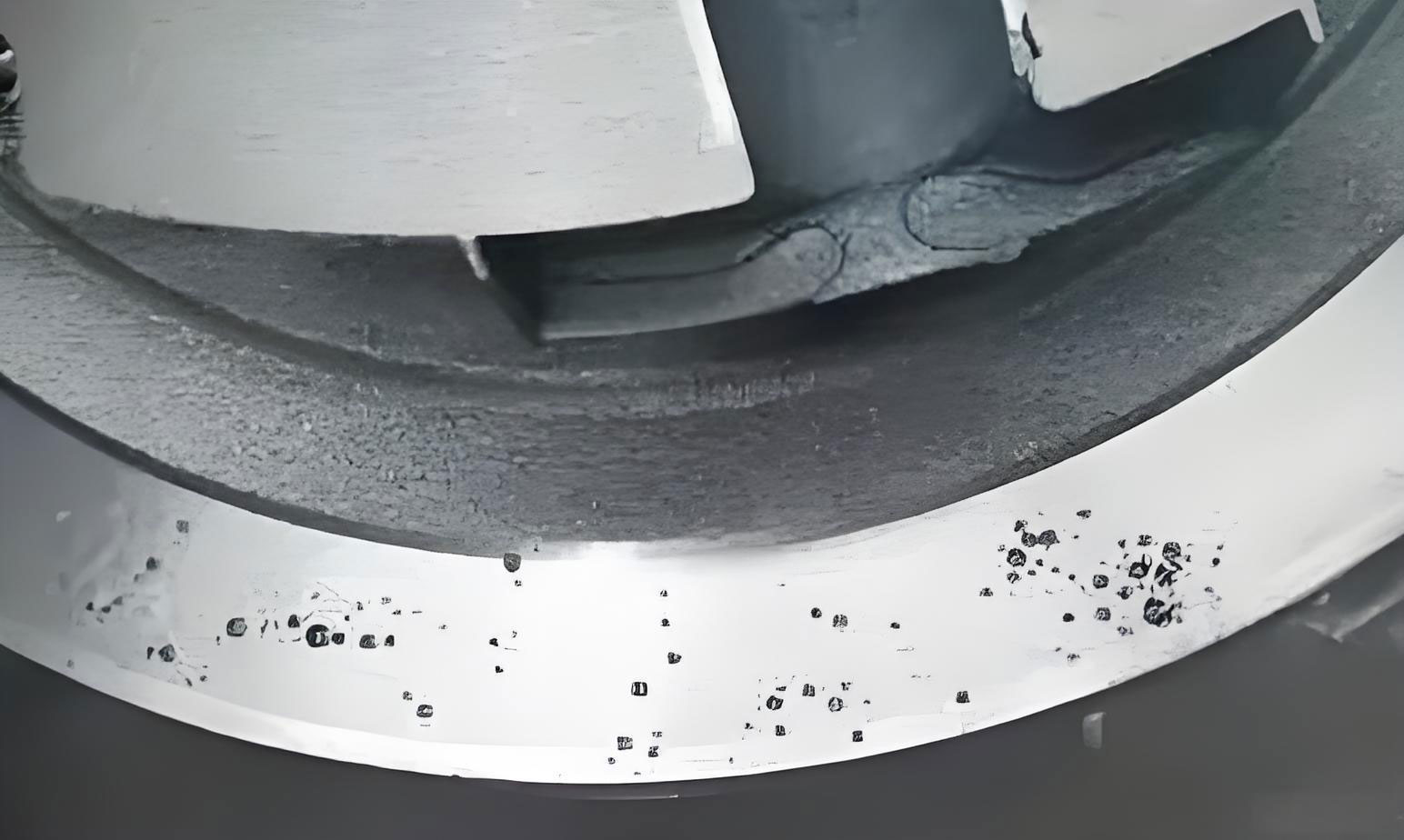
The image above illustrates a classic manifestation of this defect—micro-porosity at the root of a bolt boss, a direct result of ineffective feeding of an isolated thermal node during the final stages of mushy solidification.
2. Analysis of Failed Conventional Remediation Attempts
Before arriving at the final solution, we systematically trialed and evaluated several standard foundry practices aimed at mitigating shrinkage in casting. All initial attempts focused on the local management of the hot spot’s thermal field but neglected the systemic feeding requirements dictated by equilibrium solidification theory. The table below summarizes these attempts and their shortcomings.
| Solution Attempt | Mechanism / Rationale | Implementation | Result & Reason for Failure |
|---|---|---|---|
| Chills (Internal & External) | Accelerate local solidification to reduce the size and duration of the hot spot, shifting the solidification sequence. | Placement of chromite or cast iron chills directly against the bolt boss in the mold or core. | Partial improvement, but persistent shrinkage in casting at the boss root. Chills promote directional solidification but do not provide a liquid feed source. In mushy alloys, rapid chilling can even prematurely seal off feeding paths. |
| Core Inserts in Boss | Reduce the effective modulus of the hot spot by replacing a volume of metal with sand, thereby minimizing the thermal mass. | A sand core placed inside the bolt boss cavity during molding. | Defect persisted, often just below the core at the junction with the wall. The fundamental issue of feeding the remaining metal volume at the root was not addressed. The core also introduced complexity and potential for veining or burn-in defects. |
| Direct Side Riser on Boss | Provide a dedicated source of liquid metal for feeding the isolated hot spot. | A conventional necked riser placed adjacent to the bolt boss. | Unreliable, with ~40% of parts still showing shrinkage in casting. The mushy solidification made the riser neck “heal” or bridge before feeding was complete. Low casting yield and high cleaning cost. |
The consistent failure of these localized methods underscored a critical lesson: treating the symptom (the hot spot) without addressing the underlying pathology (the systemic lack of timely, pressurized feed metal during the critical solidification period) is ineffective for mushy-solidifying alloys. The problem of shrinkage in casting required a holistic redesign of the filling and feeding system.
3. The Equilibrium Solidification Solution: Principle and Application
Equilibrium Solidification Technology, as developed by Prof. Wei Bing, provides the theoretical framework we successfully applied. Its core tenets directly counteract the challenges posed by mushy solidification and graphite expansion in ductile irons:
- Utilize Graphite Expansion Pressure: In ductile irons, the precipitation of graphite during eutectic solidification causes a volume expansion. The gating/risering system must be designed to harness this internal pressure to aid feeding, not fight against it by providing excessive external liquid feed too early.
- Short, Intensive Feeding: Feeding should be intense and occur over a short distance and time, synchronized with the period of maximum contraction and subsequent expansion.
- Contact Feeding at the Hot Spot: The most effective way to feed an isolated hot spot is to have the source of feed metal (the riser or a gating channel) in direct contact with, or immediately adjacent to, that hot spot.
- “Wide, Thin, and Short” Riser Necks: This specific design promotes rapid heat transfer, ensures the neck remains open longer than the hot spot, and allows the riser to be easily removed.
3.1 Mathematical Basis for Design
The design process begins with calculating the modulus ($M$) of critical sections. For a rectangular bolt boss, the modulus is approximated as:
$$
M_{boss} = \frac{a \times b}{2(a + b)}
$$
for a boss of thickness/width $a$ and height $b$, neglecting one end. The riser and its neck must be designed so that the modulus of the riser neck ($M_n$) is between that of the casting hot spot ($M_c$) and the riser itself ($M_r$), following the sequence:
$$
M_c < M_n < M_r
$$
Furthermore, to ensure the neck stays open to transmit feeding pressure, its solidification time ($t_n$) must be longer than that of the hot spot ($t_c$) but shorter than the riser ($t_r$). Using Chvorinov’s Rule:
$$
t = k \cdot M^2
$$
where $k$ is the mold constant. Therefore, the condition $t_c < t_n < t_r$ is satisfied by ensuring $M_c < M_n < M_r$.
The “wide and thin” neck geometry (e.g., a rectangular cross-section with a high width-to-thickness ratio) maximizes its cross-sectional area for feeding flow while minimizing its modulus, striking the right balance.
3.2 Practical Implementation on the Exhaust Manifold
We radically redesigned the entire pouring and feeding system for a problematic manifold with multiple isolated bolt bosses and pads. The before-and-after comparison is detailed below:
| System Parameter | Original (Failed) Design | Optimized Equilibrium Design | Rationale for Change |
|---|---|---|---|
| Gating Approach | Bottom gating via multiple ingates along the base. | Middle gating with strategically placed ingates. | Bottom gating leads to severe temperature stratification, with the top (where bosses often are) being coldest. Middle gating creates a more uniform thermal field and allows risers to be placed in hotter regions. |
| Riser Function & Placement | Risers placed only on large collector volumes; bolt bosses ignored or treated with chills. | Risers are integral parts of the gating system. Ingress points are designed as contact hot spot feeders. | Transforms the gating system from merely a filling conduit into a distributed feeding network. Liquid metal enters directly through a riser neck in contact with a critical boss. |
| Feeding Strategy for Clustered Hot Spots | Each boss treated as an independent problem. | A single, strategically sized riser is used to feed a cluster of 3-4 adjacent bolt bosses. | Groups isolated hot spots into a “feeding group,” increasing efficiency. The riser is sized for the combined modulus of the group, and its multiple necks are designed to contact or be extremely close to each boss. |
| Riser Neck Design | Conventional circular necks with high modulus. | Wide, thin, and short rectangular necks (e.g., 15mm wide x 4mm thick). | Maximizes feeding contact area and heat transfer. The low modulus ensures it solidifies after the boss but before the riser body, acting as a “thermal valve.” |
| Auxiliary Cooling | Extensive use of chills on bosses. | Elimination of all chills on bolt bosses. | Chills disrupt the controlled thermal gradient needed for the equilibrium feeding sequence. The contact-feeding riser provides both thermal mass and liquid feed. |
The schematic change was profound. Instead of metal flowing from the bottom and hoping it would somehow feed downward-facing bosses, the new system introduced metal at a mid-height level directly into feeder necks attached to the critical bosses. This ensured that the last metal to enter the mold was also the metal destined to feed the last regions to solidify.
4. Results and Validation
The implementation of the equilibrium solidification design completely eliminated shrinkage in casting defects in the previously problematic manifolds.
4.1 Quantitative and Qualitative Results
| Evaluation Method | Original Process Result | Optimized Process Result |
|---|---|---|
| Visual Inspection of Rough Castings | Surface sinks or draws visible on bolt bosses. | Boss surfaces are sound and flat, with no visual sinks. |
| Sectioning & Macroscopic Examination | 100% of sectioned bosses showed internal macro/micro-shrinkage cavities at the root. | Zero shrinkage cavities found in over 50 sectioned bosses from multiple batches. Metal density is uniform. |
| Machining Validation (100% check) | Thread tapping would reveal subsurface porosity in ~60-100% of bolt holes, leading to scrap. | Zero instances of shrinkage in casting exposed during drilling, tapping, or milling of all bolt holes and pads. |
| Process Capability (Cpk) | Unacceptable (Cpk < 1.0 for defect-free castings). | Significantly improved, achieving a stable Cpk > 1.33 for critical “shrinkage-free” characteristics. |
4.2 Broader Application and Transferability
The success of this methodology is not product-specific. We have successfully transferred the same design principles to over a dozen different exhaust manifold and turbine housing designs in Si-Mo, high-nickel austenitic, and even standard ductile iron. In every case, the systematic application of contact feeding and gating-integrated risering has drastically reduced or eliminated shrinkage in casting in isolated hot spots. For instance, another complex manifold with 12 separate bolt bosses was redesigned. Sectioning of sample castings confirmed the complete absence of shrinkage in casting in all 12 locations, validating the robustness of the approach.
5. Complementary Process Controls
While the gating/risering design is paramount, its success is underpinned by strict control of ancillary processes:
- Chemistry Control: Maintaining the correct balance of carbon and silicon is critical. High silicon promotes graphitization and the associated expansion, but excessive loss of carbon equivalent during melting and treatment can reduce this beneficial expansion. We aim for the upper limit of the specification to ensure robust graphitization potential.
- Melting and Treatment: “Fast melt, fast pour” is our mantra. Minimizing hold time reduces oxidation and temperature loss. Tight control of nodularizing and inoculating practices ensures a fine, uniform graphite structure, which promotes a more predictable and uniform expansion behavior.
- Pouring Temperature: An optimal window must be maintained. Too low, and fluidity suffers, causing mistuns; too high, and total contraction volume increases, while mold penetration risks rise. We typically target a narrow range of 1380-1420°C for these Si-Mo alloys.
6. Conclusion
The problem of shrinkage in casting in high-performance Si-Mo nodular iron exhaust manifolds is fundamentally a problem of feeding system design misaligned with the alloy’s solidification characteristics. Conventional methods focusing on localized cooling are ineffective against the mushy solidification and isolated hot spots typical of these castings. The successful resolution lies in the rigorous application of Equilibrium Solidification Technology principles.
The key to eliminating shrinkage in casting is to design the gating system itself as a distributed feeding network. This is achieved by:
- Employing middle or top gating to establish a favorable temperature gradient.
- Designing ingates as wide, thin, and short riser necks that make direct contact with, or are in very close proximity to, the isolated thermal nodes.
- Sizing risers to feed clusters of hot spots, not just large volumetric sections.
- Harnessing the internal graphite expansion pressure by ensuring the riser necks remain open as feeding channels during the critical contraction-expansion period.
This holistic approach, combined with stringent control over metallurgy and pouring parameters, has transformed the production of these complex castings. It has moved scrap rates for shrinkage in casting from near 100% to near 0%, proving that even the most challenging feeding problems in advanced cast irons can be solved through scientifically guided engineering of the solidification process.