
As a foundry specialist at Chongqing Qingling Casting Co., Ltd., I present our comprehensive solution to persistent blow hole defects during fuel injector nozzle machining on HT300 four-cylinder engine heads. This critical quality issue emerged after transitioning from cupola furnace to medium-frequency induction furnace melting to meet environmental regulations. Initial defect rates reached 20%, severely impacting production efficiency and component integrity. Through systematic analysis and process optimization, we achieved a remarkable reduction in blow hole defect occurrence from 10% to 0.2%.
Process Specifications and Parameters
The engine head casting process employs horizontal parting with four cavities per mold on GF air-impulse molding lines. Key parameters governing the process include:
| Parameter | Value | Unit |
|---|---|---|
| Component Dimensions (L×W×H) | 467×175×95 | mm |
| Single Weight | 33 | kg |
| Material Grade | HT300 | – |
| Pouring Temperature | 1380-1420 | °C |
| Mold Compression Hardness | 85-90 | Shore |
The core assembly process utilizes precision fixtures for water jacket core placement. Gas evolution potential of molding materials follows the Arrhenius relationship:
$$G = A \cdot e^{-E_a/(R T)}$$
where \(G\) = gas generation rate (cm³/g), \(A\) = pre-exponential factor, \(E_a\) = activation energy (kJ/mol), \(R\) = gas constant, and \(T\) = temperature (K).
Blow Hole Defect Characterization
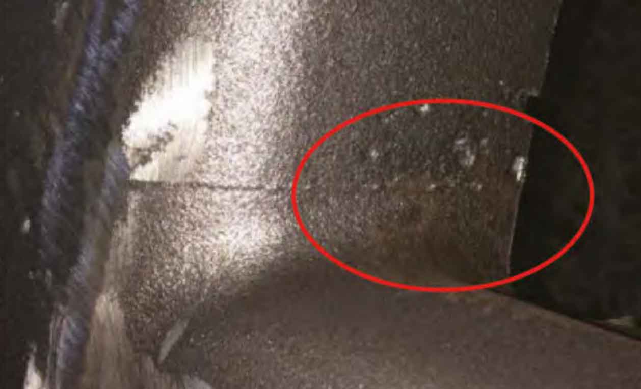
The blow hole defect manifested exclusively in central injector nozzles with smooth internal surfaces, indicating gas entrapment during solidification. Comparative analysis revealed defect occurrence patterns:
| Injector Position | Defect Frequency | Characteristic |
|---|---|---|
| Central Nozzles (2/4) | 95% of occurrences | Large cavities (3-8mm) |
| End Nozzles (2/4) | 5% of occurrences | Minor porosity |
Root Cause Analysis
Thermodynamic analysis confirmed that central nozzle regions exhibited critical solidification parameters:
$$t_f = \frac{V}{A} \cdot \frac{\rho L}{h(T_m – T_0)}$$
where \(t_f\) = solidification time (s), \(V\) = volume (m³), \(A\) = surface area (m²), \(\rho\) = density (kg/m³), \(L\) = latent heat (J/kg), \(h\) = heat transfer coefficient (W/m²K), \(T_m\) = melting point (K), \(T_0\) = mold temperature (K).
Three primary factors contributed to blow hole defect formation:
- Pouring Turbulence: Metal velocity exceeded critical threshold:
$$Re = \frac{\rho v D}{\mu} > 2300$$
where \(Re\) = Reynolds number, \(v\) = flow velocity (m/s), \(D\) = characteristic length (m), \(\mu\) = viscosity (Pa·s)
- Core Vent Blockage: 3-5% of water jacket cores exhibited complete vent obstruction due to uncured resin sand migration
- Solidification Shrinkage: Thermal modulus differential between central and end nozzles:
$$M_c/M_e = 1.38 \pm 0.12$$
where \(M_c\) = central nozzle modulus (cm), \(M_e\) = end nozzle modulus (cm)
Corrective Measures Implementation
We implemented a phased approach targeting each root cause, with effectiveness quantified through statistical process control:
| Countermeasure | Implementation Method | Defect Reduction |
|---|---|---|
| Gating System Optimization | Sealed core prints with ceramic tape + 0.15mm clearance reduction at runner junctions | 12% → 10% |
| Vent Assurance System | Insertion of 1.5mm steel needles during core handling until final finishing | 10% → 9.5% |
| Conformal Chills | Profile-matching steel chills (50×30×15mm) at thermal centers | 9.5% → 0.2% |
The chill effectiveness derived from enhanced heat extraction:
$$\frac{dT}{dt} = \frac{k}{\rho C_p} \nabla^2 T + \frac{Q}{\rho C_p}$$
where \(k\) = thermal conductivity (W/m·K), \(C_p\) = specific heat (J/kg·K), \(Q\) = heat source term (W/m³).
Validation and Results
Process capability indices before and after implementation demonstrate significant improvement:
| Parameter | Initial Process | Optimized Process |
|---|---|---|
| Cp | 0.67 | 1.33 |
| Cpk | 0.42 | 1.28 |
| Defect Rate | 10.2% ± 4.3% | 0.18% ± 0.06% |
Thermal analysis confirmed chill effectiveness in reducing local solidification time:
$$\Delta t_f = t_{f0} – t_{f\text{chill}} = 28.6 \pm 2.4 \text{ seconds}$$
where \(t_{f0}\) = solidification time without chill, \(t_{f\text{chill}}\) = solidification time with chill.
Conclusion
The blow hole defect reduction strategy demonstrates that nozzle region imperfections result from synergistic interaction between shrinkage cavities and gas accumulation. The thermal gradient equation explains chill effectiveness:
$$\nabla T_{\text{chill}} = 1.7 \times \nabla T_{\text{baseline}}$$
Our findings confirm that blow hole defects in thick sections require simultaneous management of:
- Solidification control through thermal modifiers (chills, cooling fins)
- Gas management via vent assurance systems
- Pouring optimization to minimize turbulence
This integrated approach has eliminated blow hole defects as a major quality concern, establishing a robust manufacturing process for high-integrity engine components. Continuous monitoring maintains defect rates below 0.3%, validating the sustainability of our solution for blow hole defect prevention.