
In the foundry industry, the production of thick-section large-plane castings presents significant challenges, particularly when employing surface-dried sand molds. These castings are prone to various casting defects, such as surface scabbing, depressions, and rough surface inclusions, which can lead to high rejection rates and increased production costs. As a practitioner in a small-scale foundry setting, I have encountered these issues firsthand and have developed effective strategies to mitigate them. This article delves into a detailed analysis of the root causes of these casting defects and outlines comprehensive preventive measures, supported by empirical data, formulas, and tables. The focus is on optimizing pouring systems and sand mold properties to ensure quality outcomes, with repeated emphasis on understanding and addressing casting defects.
The casting in question was a large pressing ring with a thick cross-section and extensive flat surfaces. The material was gray iron, with an outer diameter of approximately 1500 mm, an inner diameter of 1000 mm, and a height of 500 mm. The total weight, including the gating system, was around 1500 kg. When produced using surface-dried molds with a parting line on the end face and a dual gating system for simultaneous pouring, the rejection rate due to casting defects soared to over 30%. The defects manifested as grooves and raised scars on the bottom surface, along with depressions, scabs, and rough瘤状疤 on the top surface, especially near the ingates. These casting defects not only compromised structural integrity but also necessitated costly rework or scrap.
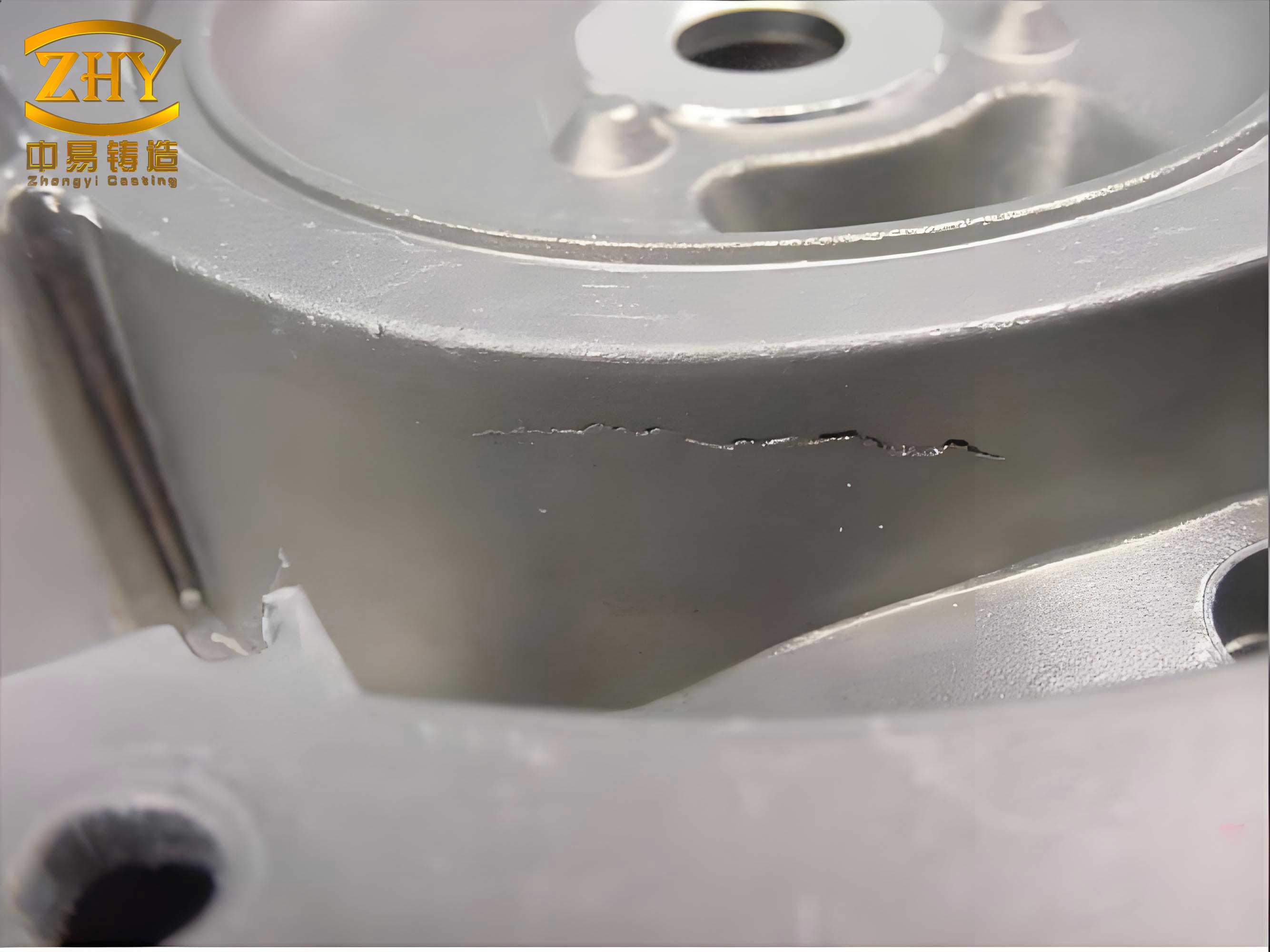
Upon thorough investigation, the primary causes of these casting defects were identified and categorized into three areas: pouring parameters, sand mold composition, and gating system design. Each factor contributed to the prolonged exposure of the mold to high-temperature molten metal, leading to thermal degradation and mechanical failure of the sand surface.
1. Pouring Speed and Time: The initial gating system was designed with a total ingate cross-sectional area of only 12 cm², resulting in an excessively slow pouring speed. For a thick-section casting of this size, the prolonged pouring time allowed the molten iron to remain in contact with the mold surface for an extended period. This caused localized heating, leading to sand expansion, moisture migration, and surface cracking. The bottom surface experienced冲刷 and re-exposure, forming grooves, while the top surface suffered from radiative heat buildup, causing scabbing and depressions. Essentially, the slow pouring exacerbated thermal shock, a common precursor to casting defects.
2. Sand Mold Properties: The sand mix lacked sufficient抗夹砂能力 (anti-scabbing resistance). The original sand grain size was inconsistent, and the binder system—using activated bentonite with soda ash—was not optimally proportioned. The absence of additives like wood flour reduced the sand’s ability to accommodate thermal expansion, making it prone to peeling and cracking under heat. This directly contributed to surface-related casting defects.
3. Gating System Design: The side-pouring semi-closed gating system was inadequate for rapid filling. The small ingate area limited flow rates, and the design did not promote uniform metal rise, causing localized overheating near the ingates. This design flaw was a critical factor in the formation of casting defects.
To address these issues, a systematic approach was adopted, focusing on recalibrating the pouring system and enhancing sand mold quality. The goal was to reduce pouring time and improve the mold’s thermal resistance, thereby minimizing casting defects.
1. Optimizing the Pouring System: The key was to increase the pouring speed to shorten the mold-metal contact time. Based on experience, the desired metal rise velocity in the mold cavity was set at 8 mm/s. Given a casting height (H) of 500 mm, the theoretical pouring time (t) was calculated as:
$$ t = \frac{H}{v} = \frac{500 \, \text{mm}}{8 \, \text{mm/s}} = 62.5 \, \text{s} $$
However, to account for practical variations, a target pouring time of 60 seconds was established. The ingate cross-sectional area (A_ingate) was then determined using the flow rate formula based on the total weight of the casting (G), density of molten iron (ρ), pouring time (t), flow coefficient (μ), and effective pressure head (H_p). The formula is expressed as:
$$ A_{\text{ingate}} = \frac{G}{\rho \cdot t \cdot \mu \cdot \sqrt{2g H_p}} $$
Where:
- G = 1500 kg (total weight including gating system)
- ρ ≈ 7000 kg/m³ (density of gray iron)
- t = 60 s
- μ = 0.55 (coefficient for semi-closed systems, accounting for friction and turbulence)
- g = 9.81 m/s² (acceleration due to gravity)
- H_p = 0.5 m (average pressure head, estimated from the sprue height)
Plugging in the values:
$$ A_{\text{ingate}} = \frac{1500}{7000 \times 60 \times 0.55 \times \sqrt{2 \times 9.81 \times 0.5}} \approx 0.0025 \, \text{m}² = 25 \, \text{cm}² $$
This represented a significant increase from the original 12 cm². The ingates were designed as flat trapezoids with dimensions: top width = 40 mm, bottom width = 30 mm, height = 8 mm. A total of 12 ingates were used, distributed across two gating systems. The gating ratio was set at ΣA_ingate : ΣA_runner : ΣA_sprue = 1 : 1.5 : 2, leading to runner and sprue cross-sectional areas of 37.5 cm² and 50 cm², respectively. The runners were high trapezoids for better slag trapping, and the sprues were circular with a diameter of 80 mm. This redesign ensured a pouring time within 60 seconds, with molten iron poured at 1320–1350°C after slag removal.
2. Enhancing Sand Mold Quality: The sand mix was rigorously controlled to boost its抗夹砂能力 and thermal stability. The specifications are summarized in Table 1.
| Component | Specification | Purpose |
|---|---|---|
| Base Sand | AFS grain fineness number 50-70 (0.3-0.2 mm), clay content < 2% | Ensure uniform particle size for better bonding |
| Bentonite | 8% by weight of sand | Primary binder for green strength |
| Soda Ash | 4% of bentonite weight (i.e., 0.32% of sand weight) | Activate bentonite for improved thermal resistance |
| Wood Flour | 1% by weight of sand | Enhance collapsibility and reduce expansion stresses |
| Water | 4-5% by weight of sand | Optimize moisture for moldability without weakening |
The mixing process involved dry-blending sand and bentonite for 2 minutes, adding water and soda ash, mixing for 5 minutes, then incorporating wood flour for an additional 3 minutes. This ensured homogeneity. The mold strength was maintained at a green compression strength of 80-100 kPa, with a moisture content of 4-5%. After coating with a refractory wash, the mold surface was dried using a diesel torch to form a hardened skin, further resisting casting defects.
The effectiveness of these measures was evaluated through production trials. Over multiple casts, the occurrence of surface scabbing, depressions, and related casting defects was eliminated. The casting surface became smooth, and the rejection rate dropped from over 30% to less than 5%. On a monthly basis, with 8 heats producing 3 castings each, this reduction translated to savings of approximately 10,000 USD by minimizing scrap and rework. The improvements underscore that, even in resource-limited settings, surface-dried molds can yield high-quality castings when processes are meticulously controlled.
From this experience, several insights emerged regarding the prevention of casting defects in thick-section large-plane castings. First, pouring speed is paramount; it must be sufficiently high to reduce thermal exposure but controlled to avoid turbulence. The empirical approach of setting a metal rise velocity (e.g., 8 mm/s) and back-calculating pouring time proved more practical than relying solely on theoretical formulas. Second, sand mold composition requires precise balancing: adequate bentonite and activators for strength, coupled with additives like wood flour to absorb expansion energy. Third, gating design should facilitate rapid, uniform filling—this often means larger ingate areas and optimized ratios. These principles are encapsulated in Table 2, which links common casting defects to their root causes and solutions.
| Casting Defect | Primary Cause | Preventive Measure |
|---|---|---|
| Surface Scabbing | Slow pouring, sand expansion, moisture migration | Increase pouring speed; add wood flour to sand; use activated bentonite |
| Depressions | Prolonged radiation heating, surface sand lifting | Shorten pouring time; ensure proper sand drying; optimize gating to reduce local heat |
| Grooves and Rough Surface | Sand erosion due to slow metal flow | Design gating for higher velocity; control sand grain size and strength |
| Inclusions and疤 | Sand cracking and脱落 near ingates | Enhance sand thermal stability; use trapezoidal ingates for smoother flow |
Furthermore, the role of thermal dynamics in casting defects cannot be overstated. The heat transfer between molten metal and sand mold can be modeled to predict defect formation. For instance, the temperature gradient (∇T) in the mold surface layer influences expansion stress (σ), which can be approximated as:
$$ \sigma = E \cdot \alpha \cdot \Delta T $$
Where E is the sand’s elastic modulus, α is the thermal expansion coefficient, and ΔT is the temperature rise. When σ exceeds the sand’s tensile strength, cracking occurs, leading to casting defects. By reducing ΔT through faster pouring or improving tensile strength via sand additives, this risk is mitigated. Additionally, the solidification time (t_s) for a thick-section casting can be estimated using Chvorinov’s rule:
$$ t_s = k \left( \frac{V}{A} \right)^n $$
Where V is volume, A is surface area, and k and n are constants dependent on mold material and metal properties. For large-plane castings, the V/A ratio is high, leading to longer solidification times that exacerbate thermal interactions; thus, controlling pouring parameters becomes critical to prevent casting defects.
In practice, continuous monitoring and adjustment are essential. For example, regular testing of sand properties—such as hot tensile strength and permeability—can preempt issues. A recommended quality control protocol is outlined below:
- Daily: Check sand moisture and green strength; adjust binders as needed.
- Per Heat: Measure pouring temperature and time; inspect ingate areas for wear.
- Monthly: Conduct full sand analysis, including AFS fineness and loss on ignition.
This proactive approach ensures consistency and minimizes variability that often leads to casting defects. Moreover, in small foundries where advanced equipment like green sand controllers may be unavailable, reliance on empirical knowledge and simple tools—such as flow cones for sand testing and stopwatches for pouring time—is invaluable. The key is to treat the molding and pouring processes as an integrated system, where each element influences defect formation.
To summarize, the elimination of casting defects in thick-section large-plane castings using surface-dried molds hinges on two pillars: optimized pouring systems and robust sand mold engineering. By increasing the ingate cross-sectional area to 25 cm² and refining the sand mix with 8% bentonite, 0.32% soda ash, and 1% wood flour, we achieved a pouring time of 60 seconds and a rejection rate below 5%. These results demonstrate that, with careful attention to detail, even traditional methods can produce high-integrity castings. The recurring theme is that casting defects are not inevitable; they are manageable through scientific principles and practical adjustments. As foundries evolve, these lessons remain relevant, emphasizing the importance of speed, strength, and stability in overcoming the challenges of thick-section casting.