
The reliable production of high-integrity shell castings for critical applications, such as the spray pump housing in nuclear power plants, presents a significant metallurgical and engineering challenge. These components are classified as nuclear safety-related, necessitating performance levels far exceeding those of conventional castings. The material, typically a low-carbon martensitic stainless steel like ZG0Cr13Ni4Mo, must exhibit exceptional mechanical properties, structural stability, and durability. Consequently, the internal integrity of these shell castings is paramount; defects like shrinkage cavities, porosity, cracks, and inclusions are categorically unacceptable. In my investigation of a recurring production issue, the most prominent defects—shrinkage cavities and porosity—were consistently found on the upper flange face and the outer edge protrusions after rough machining the riser. This problem severely impacted yield and became a primary bottleneck. This article details my comprehensive approach, utilizing AnyCasting simulation software to diagnose the root causes and implement effective process modifications that successfully eliminated these defects.
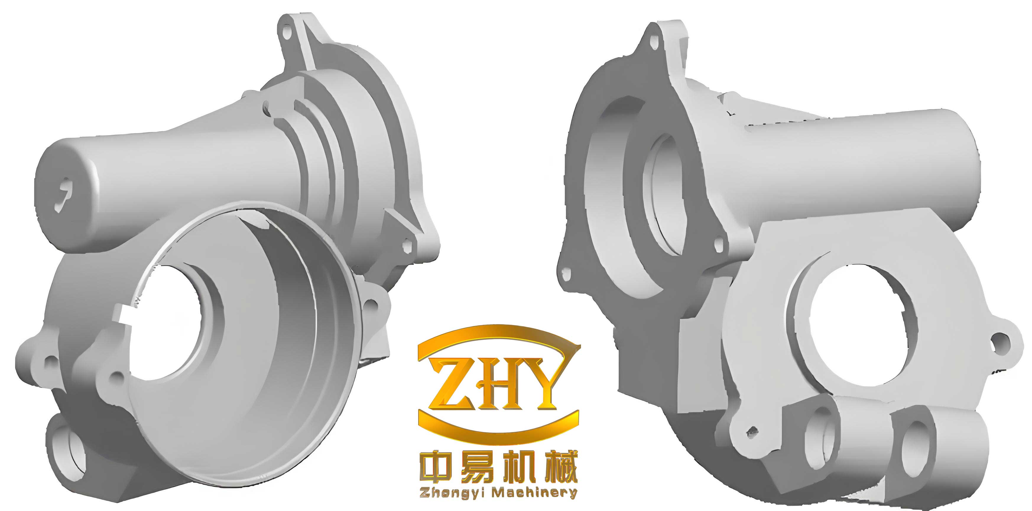
The geometry of the spray pump shell castings is inherently challenging for sound solidification. It is a medium-sized, wheel-like structure with a nominal weight of 350 kg. Key dimensions include a maximum outer diameter of 755 mm, an inner diameter of 315 mm, and a height of 338 mm. The most critical feature is the highly non-uniform wall thickness, ranging from a thin 7 mm section to a massive 90 mm section at various hubs and flanges. The lower flange contains symmetrical grooves, and its periphery features asymmetrical protrusions. The central cylindrical bore is surrounded by symmetrical, upward-spiraling cavities. This complexity, combined with the extreme variation in section size, creates isolated thermal masses (hot spots) that are prone to shrinkage defects if not properly managed through design and feeding.
The alloy of choice, ZG0Cr13Ni4Mo, adds another layer of complexity. Its solidification and phase transformation behavior directly influence defect formation. The chemical composition must be meticulously controlled, as it dictates the liquidus temperature, freezing range, and the amount of liquid and solid-state contraction.
| Element | Target Composition w(%) | Primary Influence on Solidification & Defects |
|---|---|---|
| C | ≤ 0.06 | Higher C expands freezing range, reduces fluidity, promotes shrinkage porosity. |
| Cr | 12.0 – 13.5 | Affects liquidus temperature and Cr/Ni equivalence ratio. Key for microstructure. |
| Ni | 3.5 – 4.5 | Critical for achieving low-carbon martensite. Ni/Cr ratio must be controlled (~0.36-0.44). |
| Mo | 0.4 – 0.7 | Added for strength; must be controlled to avoid adverse effects on solidification. |
| Si, Mn | ≤ 1.0 | Deoxidizers. Should be minimized as they affect equivalence ratio and fluidity. |
| S, P | ≤ 0.03, ≤ 0.02 | Tramp elements. Must be minimized as they widen freezing range and promote hot tearing. |
The total volumetric contraction during cooling is the fundamental driver of shrinkage defects. It can be modeled as the sum of three sequential stages:
$$ V_{total} = V_{liquid} + V_{solidification} + V_{solid} $$
Where a negative value indicates contraction. Shrinkage cavities form when the combined liquid and solidification contraction is not compensated by feed metal from risers. For these shell castings, the solidification shrinkage is particularly significant. The susceptibility to shrinkage can be represented by a Shrinkage Potential Index (SPI):
$$ SPI = \frac{T_L – T_S}{T_L} \cdot \beta_{sol} $$
where \(T_L\) is the liquidus temperature, \(T_S\) is the solidus temperature, and \(\beta_{sol}\) is the solidification contraction coefficient of the alloy. A larger SPI indicates a higher propensity for shrinkage defects. The production of robust shell castings requires process designs that actively counteract this potential.
The initial foundry process for these shell castings was designed with these challenges in mind but proved insufficient. It employed a bottom-gating system with a single sprue and two symmetrical runners, using ceramic tube refractories. The rationale was to achieve calm filling. A layered feeding approach was adopted: an open top riser was intended to feed the upper sections of the casting, while a side blind riser was placed lower to feed the bottom flange region. Chill plates were arranged circularly on the parting line at the bottom flange face. The pouring temperature was set at 1580°C.
I modeled this initial process in AnyCasting to visualize its shortcomings. The simulation parameters included: mesh size appropriate for the geometry, heat transfer coefficients of 41.87 W/(m²·K) for air-metal and air-mold interfaces, 3000 W/(m²·K) for chill-casting, and 1000 W/(m²·K) for chill-mold. The metal-mold interface coefficient was set as temperature-dependent. The SOL solver was used for calculation. The defect prediction module clearly identified three major problem areas, aligning perfectly with the actual defect locations on production shell castings:
| Defect Location | Defect Type | Probable Cause from Simulation |
|---|---|---|
| Upper Flange Face | Microshrinkage (Porosity) | Premature cooling of the open top riser, leading to insufficient feeding pressure and early loss of feed path. |
| Thick Section of Inner Cylindrical Wall | Macro Shrinkage Cavity | Formation of an isolated thermal hot spot. Bottom-gating left this region hottest, but feed paths from both upper and lower risers were blocked by earlier solidification of thinner surrounding sections. |
| Large Protrusion on Lower Flange Outer Edge | Macro Shrinkage Cavity | Inadequate feeding of a massive, isolated thermal mass. The single side riser could not provide sufficient feed volume or maintain an open feed channel long enough. |
The simulation confirmed that the thermal gradients established by the original process were non-directional and failed to enforce a progressive solidification sequence from the casting extremities toward the risers. The risers themselves were not the last regions to solidify. This is the fundamental failure mode for producing unsound shell castings.
My improvement strategy was multi-faceted, targeting each identified root cause without altering the component’s design. The goal was to reshape the solidification pattern decisively.
1. Enhanced Riser Feeding Efficiency: The conventional open top riser was replaced with an exothermic insulating riser sleeve. This intervention dramatically reduces the heat loss rate from the riser, maintaining its metal in a liquid state far longer. The feeding efficiency \( \eta_{riser} \) is improved as described by:
$$ \eta_{riser} = \frac{V_{feed}}{V_{riser}} \approx f \left( \frac{\Delta T_{riser}}{\Delta t_{solidification}} \right) $$
where a larger temperature difference (\( \Delta T_{riser} \)) between the riser and the casting hot spot, sustained over a longer feeding time (\( \Delta t_{solidification} \)), increases the volume of feed metal \( V_{feed} \) delivered. After pouring, a layer of exothermic topping compound was added to the riser head to provide additional superheat and delay solidification.
2. Strategic Addition of a Feeding Riser: To attack the isolated hot spot in the thick inner wall, an additional blind riser was placed directly on the central bore of the shell castings. This provided a dedicated, short feed path to the problem area, ensuring it became part of the riser’s feeding zone rather than an isolated shrinkage site.
3. Application of Conformal Chills: For the large protrusion on the lower flange, a conformal chill was fabricated to match the protrusion’s geometry. Chills work by rapidly extracting heat, effectively creating a “virtual” directional solidification front. The heat extraction can be modeled simplistically by:
$$ Q_{chill} = h_{c-c} \cdot A_{chill} \cdot (T_{casting} – T_{chill}) \cdot t $$
where \( Q_{chill} \) is the heat extracted, \( h_{c-c} \) is the chill-casting heat transfer coefficient (∼3000 W/m²K), \( A_{chill} \) is the contact area, and \( t \) is time. By accelerating solidification at the protrusion, the chill shifts the thermal center inward, extending the effective feeding range of the adjacent side riser and eliminating the isolated hot spot in these critical shell castings.
4. Refined Alloy Control: While the nominal composition was within spec, tighter control was enforced based on the metallurgical analysis. The Ni/Cr equivalence ratio was targeted at the optimal mid-range. Residual elements like Si and Mn were pushed to the lower end of their ranges to improve fluidity and reduce the freezing range, thereby minimizing the inherent shrinkage potential (SPI) of the alloy used for these shell castings.
| Process Modification | Target Defect Area | Mechanism of Action |
|---|---|---|
| Exothermic Insulating Top Riser | Upper Flange Porosity | Dramatically extends riser liquid life, improves feeding pressure and duration. |
| Additional Central Blind Riser | Inner Wall Shrinkage Cavity | Provides direct, short feed path to isolated thermal center, making it riser-fed. |
| Conformal Chill on Flange Protrusion | Flange Edge Shrinkage Cavity | Accelerates local solidification, extends effective feeding range of side riser, eliminates hot spot. |
| Tighter Alloy Control | General Reduction in Shrinkage Tendency | Optimizes freezing range and fluidity, reducing the fundamental volumetric deficit to be fed. |
Simulating the optimized process in AnyCasting yielded a markedly different result. The temperature gradient plots showed a clear, unidirectional progression. The solidification sequence visualization confirmed that the three shell casting problem areas now solidified before their respective feeding risers. Most importantly, the defect prediction module showed a complete absence of shrinkage indicators within the casting body. Any predicted shrinkage was confined to the riser volumes, which is the intended outcome—defects are relegated to the sacrificial feed metal.
The production trial based on this optimized design validated the simulation. The resulting spray pump shell castings were visually sound. Non-destructive testing via ultrasonic examination confirmed the internal integrity: the shell castings were dense, free from shrinkage cavities, porosity, and other disqualifying defects. The mechanical properties met all specifications for the nuclear-grade application. The process yield increased substantially, resolving the critical production bottleneck.
| Evaluation Metric | Original Process | Optimized Process |
|---|---|---|
| Simulation Defect Prediction | Shrinkage in 3 casting locations | No shrinkage in casting; only in risers |
| UT Inspection Result | Reject due to shrinkage/porosity | Acceptable; no internal defects |
| As-Cast Surface Quality | Defects visible after rough machining | Sound, no surface sinks or imperfections |
| Production Yield Impact | Low, process bottleneck | High, consistent quality achieved |
This case underscores the indispensable role of solidification simulation in modern foundry engineering, especially for complex, high-reliability shell castings. The use of AnyCasting software provided a virtual proving ground, enabling a precise diagnosis of the flawed thermal gradients and feeding mechanisms in the original process. The systematic improvements—focused on enhancing riser efficiency, providing direct feed paths, using chills to control local solidification rates, and refining metallurgy—transformed the solidification pattern. The successful outcome demonstrates that a physics-based, simulation-guided approach is highly effective for solving persistent quality issues in critical casting production, ensuring the manufacturing of defect-free shell castings that meet the most stringent nuclear safety standards.