
In our high precision investment casting facility, we have systematically addressed the environmental challenges arising from every stage of production. From wax injection to final finishing, pollution in the form of dust, fumes, wastewater, noise, and solid waste is inevitable. However, through rigorous engineering controls and continuous improvement, we have achieved compliance with stringent emission standards while maintaining the quality and precision that our casting process demands. This article documents our comprehensive anti-pollution measures, focusing on dust collection, fume treatment, wastewater management, noise abatement, and solid waste handling, all within the context of high precision investment casting.
Pollution Sources in High Precision Investment Casting
The production flow of high precision investment casting involves mechanical and chemical reactions that generate various pollutants. The primary raw materials include steel scrap (containing Ni, Cr, Mn, Si, C), zircon sand and flour (melting point 1852°C, boiling point 4377°C), mullite (aluminosilicate refractory, refractoriness 1750°C), silica sol (SiO₂, water, hydroxyl groups, viscosity ≤ 8 mm²/s, particle size 10–15 nm), paraffin wax (ash <0.02%, linear shrinkage 0.008%–0.011%), brown corundum (Al₂O₃), aluminum or steel molds, silicone-based mold release agents, desiccants, grinding wheels, abrasive belts, and steel shot. The pollution generation points are summarized below:
| Process | Step | Pollution Type | Pollutant |
|---|---|---|---|
| Pattern Making | Wax melting | Gas, Noise, Solid | Non-methane hydrocarbons (NMHC) |
| Wax injection | Gas, Noise, Solid, Wastewater | NMHC | |
| Aluminum mold | Gas, Wastewater | NMHC | |
| Wax repair | Solid | NMHC | |
| Assembly | Gas, Solid | NMHC | |
| Cap tightening | Noise, Wastewater | NMHC | |
| Shell Building | Slurry dipping | Dust, Wastewater | Particulate matter (PM) |
| Stuccoing | Dust, Noise | PM | |
| Dewaxing | High-temperature dewaxing | Gas, Noise, Wastewater, Solid | PM |
| Shell Firing | Mold firing | Gas, Noise, Solid, Wastewater | PM |
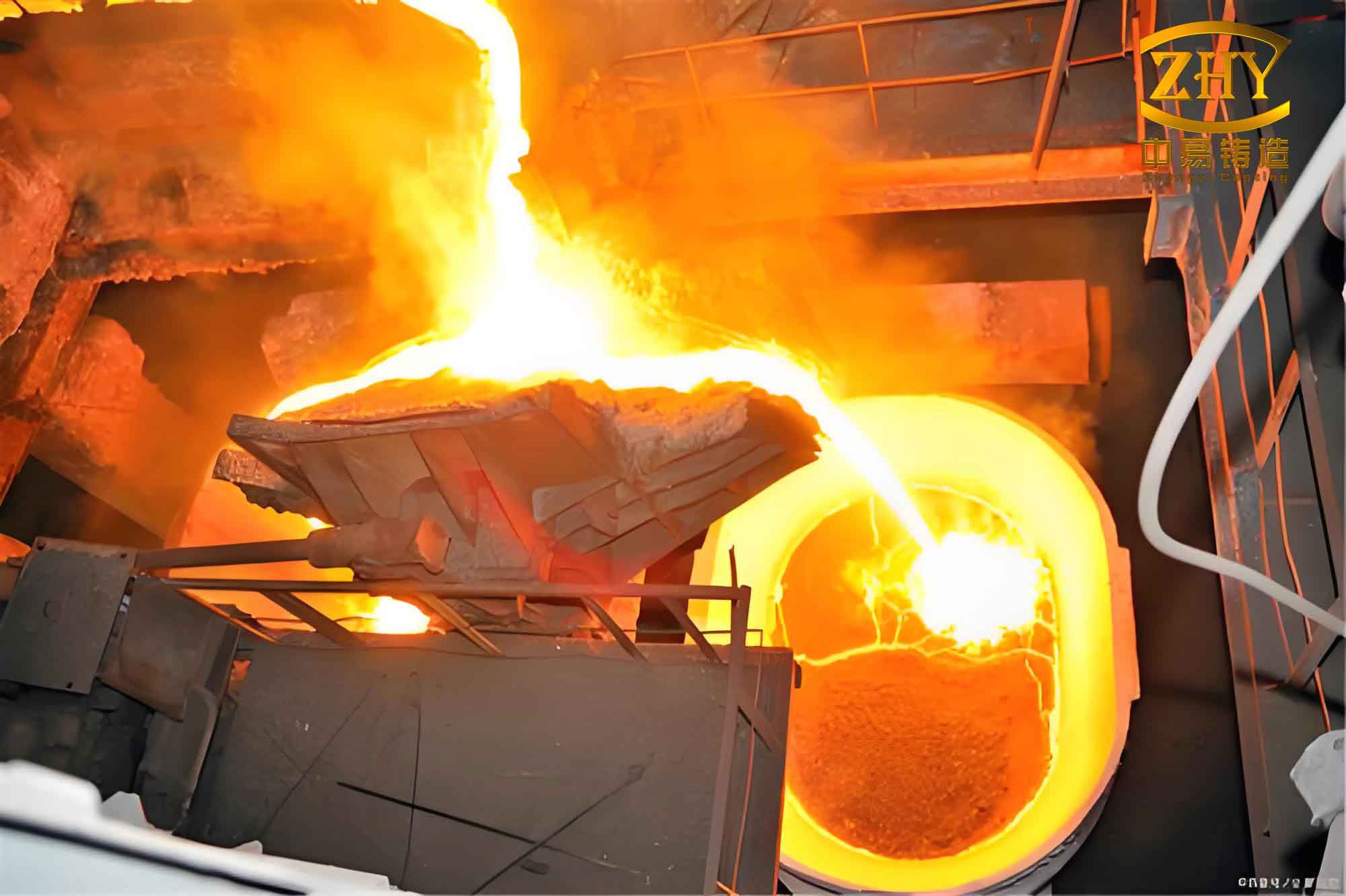
| Melting & Pouring | Steel melting | Gas, Noise, Solid, Dust | PM, CO |
| Pouring | Gas, Solid | PM | |
| Shell Removal | Vibration | Dust, Noise, Solid, Gas | PM |
| Shot blasting | Dust, Noise, Solid | PM | |
| Cutting | Abrasive cutting | Dust, Noise, Solid | PM |
| Tumbling | Dust, Noise, Solid | PM | |
| Post-processing | Grinding | Dust, Noise, Solid | PM |
| Welding | Gas, Noise, Solid | PM | |
| Straightening | Noise, Solid | PM | |
| Machining | Noise, Solid | PM | |
| Packaging | Noise, Solid | PM |
Dust Control in High Precision Investment Casting
Dust is a major concern in high precision investment casting, especially from raw material handling, shell building, and finishing operations. Our raw material warehouse is equipped with two doors—one for entry and one for exit—each fitted with a dust extraction hood measuring 2 m × 0.8 m, connected to a 15 kW fan through a 350 mm diameter duct leading to a 15 m tall chimney. The dust collector beneath is cleaned daily.
For the slurry tanks and stucco drums, circular hoods of size φ1.5 m × 0.8 m are installed, each with a 7.5 kW motor, 600 mm duct, and a 25 kW dust collector exhausting through a 17 m chimney. The shell drying room is surrounded by 800 mm diameter suction inlets to capture floor dust and particles stirred by fans, all routed via a 600 mm duct to the dust collector.
The vibration shell removal machine is enclosed in a stainless steel hood with a top-mounted 15 kW motor and a 600 mm duct connected to the dust collector. During operation, the operator removes shell fragments while the hood prevents dust escape. The shot blasting machine has two hoods: a 1000 mm × 800 mm inlet at the door and a 600 mm × 400 mm inlet at the rear, with an 800 mm main duct leading to a 30 kW dust collector. Chimney height is at least 18 m. After each hour of blasting, the machine is cleaned of accumulated dust.
Our cutting station features a semi-enclosed hood measuring 3 m × 1.5 m, with a top 15 kW motor and a 600 mm duct. An additional circular opening opposite the cutting wheel connects to another 600 mm duct for efficient capture of heavy metal dust. A metal scrap collection bin is placed beside the cutter.
The grinding station for sprue removal is fully enclosed; operators work outside the enclosure. The hood has two circular inlets: one at the top (7.5 kW) and one on the side (15 kW). A collection bin at the bottom gathers grinding debris. Both inlets connect to the central dust collector via 600 mm ducts.
We utilize ZLC pulse cartridge dust collectors. Their specifications are:
| Parameter | Value |
|---|---|
| Filtration area | 220 m² |
| Handling air volume | 38,800 m³/h |
| Reverse air consumption | 0.3 m³/min |
| Reverse air pressure | 0.5–0.7 MPa |
| Reverse air quality | Oil-free, water-free |
| Filtration velocity | 0.4–0.8 m/min |
| Pressure drop | 500–1000 Pa |
| Dust removal efficiency | 99% |
Dedicated personnel inspect the dust collectors daily. Leaks are repaired promptly, filter cartridges are cleaned or replaced when clogged, and the air‑water separator is drained regularly. Every shift ends with a 3–7 minute cleaning cycle before shutdown.
Waste Gas and Fume Treatment in High Precision Investment Casting
In our high precision investment casting shop, fumes from the medium-frequency induction furnace are captured by a stainless steel hood positioned 2 m above the furnace top. The hood measures 2 m × 1 m × 0.6 m (height), with a 7.5 kW motor and a 600 mm duct leading to a combined dust/fume collector. The fume handling system has a capacity of 21,000 m³/h, using a high-temperature bag filter rated for 200°C with a filtration area of 420 m². A 45 kW fan provides 3000 Pa pressure, duct velocity is 15 m/s, and the outlet PM concentration is ≤15 mg/m³. The chimney extends at least 18 m above ground.
Above the sand cooling area, a stainless steel hood of 3.5 m × 2.5 m is fitted with three 15 kW fans, each connected to the same fume collector via 600 mm ducts. The resulting PM emission is ≤16 mg/m³.
Our shell firing furnace is of an energy‑efficient design; wax fumes are internally combusted in the furnace chamber rather than escaping. Nevertheless, a stainless steel hood at the furnace door, equipped with a 15 kW motor and a 600 mm duct, captures residual fumes and sends them to the main exhaust system.
Wax injection machines are fitted with suction hoods (7.5 kW motor, 400 mm duct) that feed into an 800 mm main duct leading to a two-stage activated carbon adsorption system. This system handles 1500 m³/h with an 18.5 kW fan at 3000 Pa, using honeycomb activated carbon at a loading of 3.6 g/m³. The outlet NMHC concentration is maintained ≤60 mg/m³.
At the wax assembly station, a 2.5 m × 1.5 m × 0.8 m hood with a 7.5 kW motor extracts fumes through a 500 mm duct to the same activated carbon unit. The dewaxing autoclave has a 2 m × 0.8 m × 0.6 m hood above its door, also with a 7.5 kW motor and 500 mm duct to the carbon adsorber. The wax storage tank is covered by a circular hood larger than the tank mouth, with a 7.5 kW motor drawing fumes through a 500 mm duct into the activated carbon system.
Wastewater Collection and Treatment
Water used in high precision investment casting originates from wax injection cooling, wax cleaning, spray humidification in the shell room, silica sol dilution, dewaxing steam, induction coil cooling, furnace vapor condensation, domestic use, and rainwater. The main contaminants are COD, SS, ammonia nitrogen, total phosphorus, and total nitrogen. Most production water is recycled automatically; only negligible pollution remains. We have installed settling tanks and activated carbon filters at outlets to remove impurities before discharge.
The plant and workshops are served by two drainage systems: open channels for rainwater and domestic sewage, and 100 mm PPC pipes for process cooling water and wastewater. The pipe outlet passes through an activated carbon filter before entering a settling tank where lime is added to adsorb CO₂, SO₂, and other impurities. For the induction furnace cooling circuit, we use energy‑efficient cooling towers and pumps, and we add scale inhibitors, biocides, and corrosion inhibitors to control scaling, corrosion, and microbial growth.
| Equipment | Water Source | Treatment Method |
|---|---|---|
| Wax injection machine | Mold cooling water | Remove wax chips, add oil‑removing agent |
| Cleaning tanks | Wax pattern washing | Activated carbon purification, soda ash neutralization |
| Pure water tank | Slurry mixing | Filter cloth at outlet to remove solids |
| Spray humidifier | Workshop humidification | Collect, filter, and recirculate |
| Dewaxing autoclave | Steam condensate | Recover hot water, add oil‑based wax remover |
| Wax storage tank | Molten wax | Water‑wax separator, dissolve with acetone/chloroform |
| Firing furnace | Exhaust pipe condensate | Lime desulfurization/acid removal, adsorption with CaCl₂ and silica gel |
| Induction furnace | Cooling water | Add descaling agent, filter cloth circulation |
Noise Control Measures in High Precision Investment Casting
Major noise sources in our high precision investment casting facility include fans, induction furnace electrical hum, firing furnace valve switching, air compressors, vibratory shell removal, shot blasting, cutting machines, belt grinders, tumbling barrels, slurry tanks, stucco drums, wax injection machines, straightening presses, and grinders. Their sound power levels range from 75 to 85 dB(A). We employ equipment vibration isolation and workshop enclosure to reduce noise. Each machine is provided with a sealed cover or enclosure where possible, and sound‑absorbing partitions or baffles are installed between machines. Some units are fitted with silencers. These measures collectively achieve a noise reduction of more than 20 dB(A).
The outdoor noise sources are listed below:
| Source | Position (X,Y,Z) m | Sound pressure level at 1 m [dB(A)] | Control measures | Operating hours | Resultant level [dB(A)] |
|---|---|---|---|---|---|
| Fan #1 | 20, -3, 1.2 | 80 | Vibration isolation, enclosure, silencer | 18:00–8:00 | 65 |
| Fan #2 | 10, -20, 1.2 | 80 | Same | 8:00–12:00, 14:00–18:00 | 65 |
| Fan #3 | -15, -20, 1.2 | 80 | Same | 8:00–12:00, 14:00–18:00 | 65 |
| Fan #4 | 20, -20, 1.2 | 80 | Same | 8:00–12:00, 14:00–18:00 | 65 |
| Fan #5 | -25, -3, 1.2 | 80 | Same | 8:00–12:00, 14:00–18:00 | 65 |
For indoor noise sources, we apply the following calculation to predict outdoor levels. The sound pressure level at a receiver point is given by:
$$ L_p(r) = L_D(r_o) + D_C – (A_{aiv} + A_{atr} + A_{gr} + A_{bar} + A_{misc}) $$
where \(L_p(r)\) is the sound pressure level at distance \(r\) from the source, \(L_D(r_o)\) is the sound pressure level at the reference distance \(r_o\), \(D_C\) is the directivity correction, \(A_{aiv}\) is the attenuation due to atmospheric absorption, \(A_{atr}\) is the geometric divergence attenuation, \(A_{gr}\) is the ground effect, \(A_{bar}\) is the barrier attenuation, and \(A_{misc}\) represents miscellaneous effects.
The following table summarises indoor noise sources after control:
| Source | Power level [dB(A)] | Position (X,Y,Z) m | Distances to walls (E,S,W,N) m | Indoor levels at walls [dB(A)] | Building envelope TL [dB(A)] | Outdoor levels at 1 m [dB(A)] |
|---|---|---|---|---|---|---|
| 2 induction furnaces | 75 (equiv. 78) | 25, -5, 1.2 | 10, 16, 70, 2 | 58, 54, 41, 72 | 20 | 38, 34, 21, 52 |
| Firing furnace | 75 | 20, -10, 1.2 | 15, 11, 65, 7 | 51, 54, 39, 58 | 20 | 31, 34, 19, 38 |
| Air compressor | 78 | 15, -3, 1.2 | 20, 18, 60, 1 | 52, 53, 42, 78 | 20 | 32, 33, 22, 58 |
| Vibration shell remover | 85 | 20, -18, 1.2 | 15, 3, 65, 15 | 61, 75, 49, 61 | 20 | 41, 55, 29, 41 |
| 3 shot blast machines | 75 (equiv. 80) | 18, -18, 1.2 | 17, 3, 63, 15 | 55, 70, 44, 56 | 20 | 35, 50, 24, 36 |
| Cutting machine | 75 | -25, -10, 1.2 | 60, 11, 20, 7 | 39, 54, 49, 58 | 20 | 19, 34, 29, 38 |
| 5 belt grinders | 72 (equiv. 77) | -25, -8, 1.2 | 60, 13, 20, 5 | 41, 54, 51, 63 | 20 | 21, 34, 31, 43 |
| 8 shot blast machines | 75 (equiv. 78) | -20, -10, 1.2 | 55, 11, 25, 7 | 43, 57, 50, 61 | 20 | 23, 37, 30, 41 |
| 2 TIG welders | 75 | -20, -8, 1.2 | 55, 13, 25, 5 | 40, 53, 47, 61 | 20 | 20, 33, 27, 41 |
| 2 air compressors | 78 | 14, -3, 1.2 | 21, 18, 59, 1 | 52, 53, 43, 1 | 20 | 32, 33, 23, -19 |
| 4 slurry mixers | 70 (equiv. 76) | -12, -12, 1.2 | 47, 9, 33, 9 | 43, 57, 46, 57 | 20 | 23, 37, 26, 37 |
| 4 stucco machines | 75 (equiv. 81) | -12, -16, 1.2 | 47, 5, 33, 13 | 48, 67, 51, 59 | 20 | 28, 47, 31, 39 |
| 4 wax injection machines | 72 (equiv. 78) | 10, -15, 1.2 | 25, 6, 55, 12 | 50, 62, 43, 56 | 20 | 30, 42, 23, 36 |
| Dewaxing autoclave | 72 | 12, -12, 1.2 | 23, 9, 57, 9 | 45, 53, 37, 53 | 20 | 25, 33, 17, 33 |
| 5 presses | 75 (equiv. 82) | -30, -10, 1.2 | 65, 11, 15, 7 | 46, 61, 58, 65 | 20 | 26, 41, 38, 45 |
| Hydraulic press | 70 | -32, -13, 1.2 | 67, 8, 13, 10 | 33, 52, 48, 50 | 20 | 13, 32, 28, 30 |
| Handheld spectrometer | 65 | -32, -15, 1.2 | 67, 6, 13, 12 | 28, 49, 43, 43 | 20 | 8, 29, 23, 23 |
Solid Waste Management in High Precision Investment Casting
Solid waste from our high precision investment casting operation is categorized into general industrial solid waste and hazardous waste. General waste includes wax scraps, slag, used shells, metal chips, spent steel shot, welding slag, packaging waste, dust collector dust, and waste plastics. Metal‑containing waste is sold to licensed recyclers; valuable metals are sorted and recycled on site.
| Waste Type | Source | Estimated annual quantity (t) | Disposal |
|---|---|---|---|
| Wax treatment residue | Wax recovery | 1.6 | Sold |
| Wax trim | Injection/repair | 1 | Reused |
| Waste molds | Injection | 2.5 | Sold |
| Slag | Melting | 50 | Sold |
| Waste shells | Vibration removal | 210 | Sold |
| Spent steel shot | Shot blasting | 16 | Sold |
| Waste risers/gates | Cutting | 10 | Reused |
| Metal swarf | Cutting/grinding | 5 | Sold |
| Welding slag | Argon welding | 0.4 | Sold |
| Non‑conforming castings | Inspection | 30 | Reused |
| Packaging waste | Unpacking | 0.15 | Sold |
| Dust collector dust | Air pollution control | 12.5 | Sold |
| Waste filter bags (shell area) | Dust control | 0.12 | Sold |
| Waste wax (cleaning) | Cleaning | 4 | Reused |
Hazardous wastes include melting furnace dust, waste filter media, spent activated carbon, contaminated filter bags, chemical containers (bottles and drums), chimney ash from the dust collector, and firing furnace chimney ash. These are collected in a dedicated 50 m² hazardous waste warehouse, which is kept separate from raw materials and work areas. The warehouse is equipped with alarms and clear signage. Hazardous waste is dispatched every three months to licensed treatment facilities.
| Storage area (m²) | Waste type | Hazard code | Capacity (t) | Storage method | Storage period |
|---|---|---|---|---|---|
| 3 | Melting dust | HW22 | 0.5 | Sealed steel drum | 20 days |
| 2 | Dust collector chimney ash | HW22 | 0.2 | Sealed steel drum | 15 days |
| 1 | Firing furnace chimney ash | HW22 | 0.2 | Sealed steel drum | 15 days |
| 3 | Waste filter media | HW48 | 0.5 | Sealed bags | 1 month |
| 5 | Waste filter bags | HW49 | 2 | Sealed bags | 2 months |
| 2 | Spent activated carbon | HW49 | 0.3 | Sealed bags | 25 days |
| 6 | Waste chemical bottles | HW50 | 0.4 | Sealed bags | 1 month |
| 4 | Waste chemical drums | HW50 | 0.5 | Sealed steel drums | 2 months |
| 3 | Waste oil drums | HW50 | 0.2 | Sealed steel drums | 3 months |
Conclusion
Pollution can never be completely eliminated; there are always residual leakages, spills, and emissions in high precision investment casting. However, through continuous process improvement, selection of low‑pollution and energy‑efficient technologies, regular environmental monitoring, equipment upgrades, and elimination of obsolete machinery, we have significantly reduced the environmental footprint of our high precision investment casting operations. The measures described here—dust collection, fume adsorption, wastewater recycling, noise enclosure, and solid waste segregation—form the backbone of our commitment to sustainable manufacturing. We will continue to invest in pollution control and strive for even higher environmental performance in every high precision investment casting project.