
In my experience with manufacturing precision machine tool castings, I have found that achieving defect-free surfaces, particularly on导轨 surfaces where porosity and sand inclusions are unacceptable, requires meticulous attention to every stage of the铸造 process. The production of machine tool castings, such as those for high-end machine tools, demands rigorous procedures and thorough inspections to ensure dimensional accuracy and structural integrity. This article delves into the critical aspects of core making, moulding, and assembling processes, emphasizing the importance of process controls and quality checks. Throughout this discussion, the terms ‘machine tool casting’ and ‘machine tool castings’ will be frequently highlighted to underscore their relevance in industrial applications.
The foundation of producing reliable machine tool castings lies in the core making process. I always start by ensuring the core boxes are properly set up on a clean, level surface to prevent deformation during sand filling. For instance, using wedges to secure the core box is essential to maintain stability. One key step involves inspecting the core box for any distortion using specialized gauges, as even minor deviations can lead to defects in the final machine tool casting. Additionally, the placement of ventilation ropes, core irons, and lifting devices must align with工艺 requirements to facilitate proper gas escape and core strength. When working with materials like chromite sand for specific cores, such as those labeled 1a#, 4a#, and 20a#, I verify their hardening and assembly into larger cores, checking垂直度 with三角 plates before applying coatings. The timing for demolding cores is critical; for large internal cores, I wait 30 to 60 minutes and perform a nail penetration test to confirm adequate hardness. Post-demolding, cores must be placed on flat plates to avoid warping, and any imperfections are repaired using tools like grinders and patching spoons. Coating application should occur至少 40 minutes after demolding, with specific paint types and viscosities adhered to, as outlined in the following table summarizing the coating process for machine tool castings.
| Product Name | Core Number | Application Method | Primary Coating | Secondary Coating | Viscosity Range (Baumé) | Application Standard |
|---|---|---|---|---|---|---|
| Machine Tool Bed | External Cores | Brushing | FQ600 (2 coats) | FQ10 (1 coat) | 55–60 for FQ600; 16–20 for FQ10 | Coating Brushing Guidelines |
| Machine Tool Bed | Internal Cores | Dipping | Graphite (1 coat) | Brown Alumina (1 coat) | 25–30 for Graphite; 55–60 for Brown Alumina | Core Coating Specifications |
To quantify the quality assurance in core making, I often use formulas to evaluate core strength and gas permeability. For example, the core strength $\sigma_c$ can be estimated using the formula: $$\sigma_c = k \cdot \rho_s \cdot V_h$$ where $\sigma_c$ is the compressive strength, $k$ is a material constant, $\rho_s$ is the sand density, and $V_h$ is the hardening velocity. This helps in predicting the durability of machine tool castings during handling and pouring. The inspection process for core making involves multiple checkpoints, as detailed in the table below, which I routinely follow to ensure each machine tool casting meets stringent standards.
| Item No. | Inspection Content | Compliance Status |
|---|---|---|
| 1 | Verify core box and loose piece quantities are complete | Yes / No |
| 2 | Assess core box placement and storage area flatness | Yes / No |
| 3 | Check core box and loose pieces for cleanliness and release agent application | Yes / No |
| 4 | Confirm accurate installation of loose pieces | Yes / No |
| 5 | Evaluate core iron dimensions, strength, quantity, and placement | Yes / No |
| 6 | Inspect ventilation rope positioning and airflow channels | Yes / No |
| 7 | Verify core iron, ventilation ropes, and lifting devices are correctly positioned | Yes / No |
| 8 | Ensure casting identification marks are clear and accurate on cores | Yes / No |
| 9 | Assess molding sand quality for production suitability | Yes / No |
| 10 | Check sand layer thickness and reinforcement in vulnerable areas | Yes / No |
| 11 | Measure core compactness to meet requirements | Yes / No |
| 12 | Inspect sand scraping surface for evenness | Yes / No |
| 13 | Evaluate vent hole quantity and placement | Yes / No |
| 14 | Monitor core and core box protection during demolding; check for damage | Yes / No |
| 15 | Assess repair quality of any core damage | Yes / No |
| 16 | Review fine finishing of edges, fillets, and rough surfaces | Yes / No |
| 17 | Confirm coating application occurs at least 40 minutes after demolding | Yes / No |
| 18 | Check coating viscosity against specifications | Yes / No |
| 19 | Evaluate coating uniformity, direction, and absence of defects | Yes / No |
| 20 | Determine if surface baking is needed and if it meets standards | Yes / No |
| 21 | Verify attachment of合格 labels and accurate record-keeping | Yes / No |
Moving to the moulding process, I emphasize the importance of pattern preparation and sand compaction. After cleaning and applying a release agent to the pattern, I conduct a pre-moulding inspection to confirm pattern integrity and flatness. For machine tool castings, the mould must withstand the thermal stresses of pouring, so I carefully position components like ceramic tubes for runners, risers, and vent rods. In one instance, I place two ø70 mm ceramic tubes in the cope and multiple flat risers and vent rods according to design specifications. The use of chills, such as sand-insulated chills, is crucial to control solidification and prevent defects in critical areas of the machine tool casting. The demolding time varies—90 to 120 minutes for the cope and 90 to 180 minutes for the drag—and I always perform a nail test to ensure sufficient hardness before demolding. Coating the mould follows a similar protocol to core making, with specific paints applied in a consistent direction to avoid streaks or accumulations. The table below outlines the key inspection points in the moulding process for machine tool castings, which I rigorously adhere to.
| Item No. | Inspection Content | Compliance Status |
|---|---|---|
| 1 | Match mould pattern to job order specifications | Yes / No |
| 2 | Verify casting identification marks are updated correctly | Yes / No |
| 3 | Check for completeness and proper positioning of loose pieces | Yes / No |
| 4 | Confirm accurate placement of loose pieces, risers, and vents | Yes / No |
| 5 | Remove adhered sand or debris using scrapers and air guns | Yes / No |
| 6 | Apply release agent if needed and check for proper coating | Yes / No |
| 7 | Ensure availability of tools like ceramic tubes and vent ropes | Yes / No |
| 8 | Inspect pattern and plate for looseness or damage; repair if necessary | Yes / No |
| 9 | Verify presence of定位 pins on the pattern plate | Yes / No |
| 10 | Clean residual sand and iron reinforcements from flasks | Yes / No |
| 11 | Assess need for platform moulding and ensure stable base | Yes / No |
| 12 | Place hand patterns steadily on a clean platform | Yes / No |
| 13 | For large patterns, check ground flatness and support | Yes / No |
| 14 | Confirm availability of specialized chills | Yes / No |
| 15 | Verify chill numbering as per requirements | Yes / No |
| 16 | Inspect chills for dryness, cleanliness, and lack of rust | Yes / No |
| 17 | Position runners, risers, and refractory tubes according to工艺 | Yes / No |
| 18 | Check vent hole depth meets specifications | Yes / No |
| 19 | Manage initial and final sand to avoid contamination | Yes / No |
| 20 | Use cushioning like tires during large mould flipping | Yes / No |
| 21 | Avoid metal tools during demolding; adhere to demolding times | Yes / No |
| 22 | Clean loose sand and refine edges after demolding | Yes / No |
| 23 | Apply coatings at least 40 minutes after demolding | Yes / No |
| 24 | Verify coating viscosity against standards | Yes / No |
| 25 | Ensure casting identification remains intact during coating | Yes / No |
| 26 | Check if cores are set under external surfaces and handled properly | Yes / No |
| 27 | Evaluate coating for uniformity, direction, and defects | Yes / No |
| 28 | Assess chilling and mould baking for adequacy and duration | Yes / No |
| 29 | Confirm completion of tracking documents with accuracy | Yes / No |
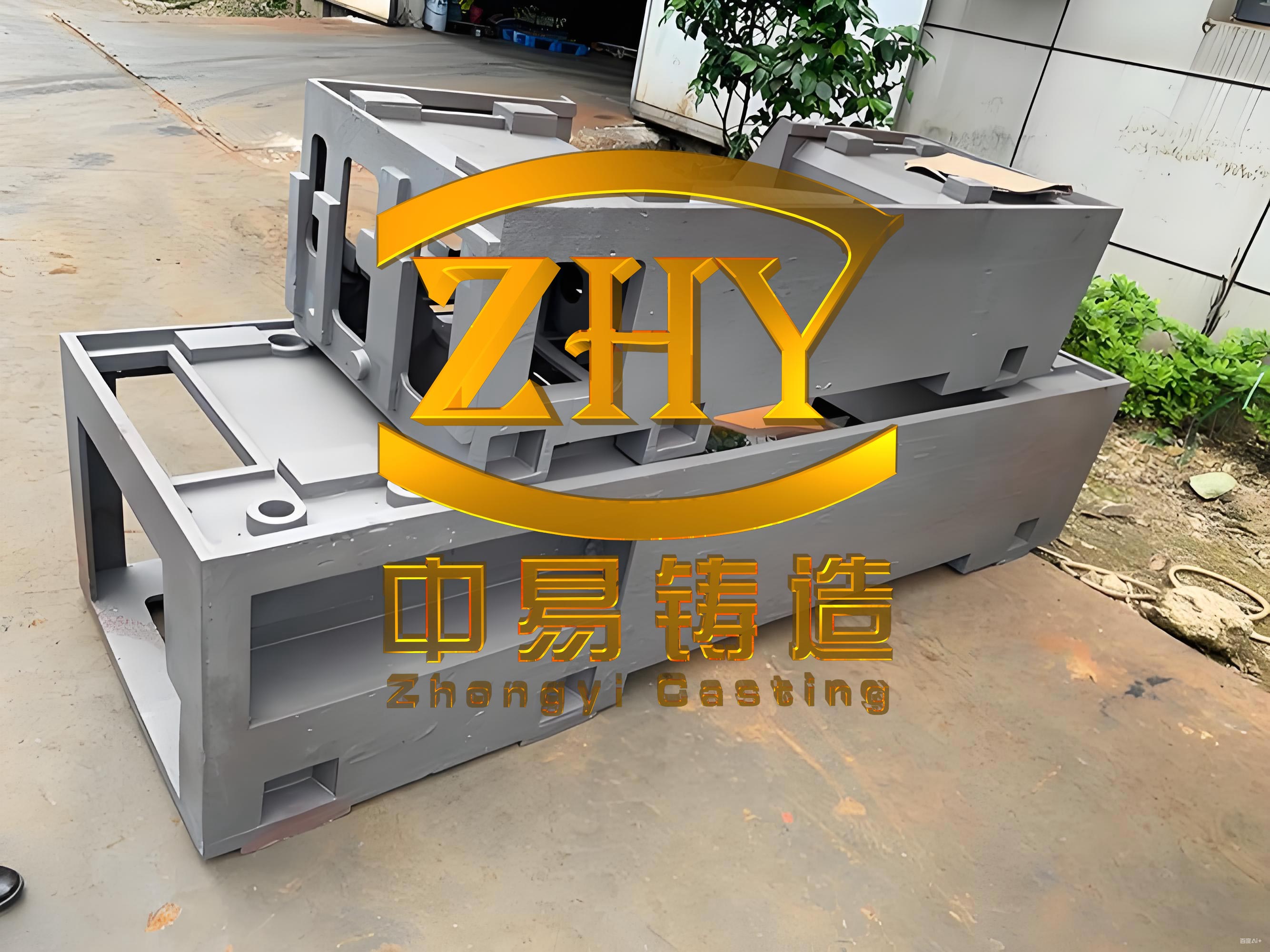
In the moulding phase, I often apply mathematical models to predict thermal behavior. For example, the solidification time $t_s$ for a machine tool casting can be estimated using Chvorinov’s rule: $$t_s = k \cdot \left( \frac{V}{A} \right)^2$$ where $V$ is the volume, $A$ is the surface area, and $k$ is a constant dependent on the mould material. This helps in optimizing riser placement to minimize shrinkage defects in machine tool castings. Additionally, the control of coating viscosity is critical; I use the formula for Baumé degree conversion: $$Bé = \frac{140}{\rho} – 130$$ where $\rho$ is the specific gravity, to ensure consistent application. The visual representation of a typical machine tool casting, as shown below, illustrates the complexity involved in achieving high-quality surfaces.
The assembling process is where all components come together, and I handle it with extreme care to prevent damage. When transferring cores and moulds, I avoid stacking and use padding like cotton mats to protect against impacts. For instance, I first place the 11# core into the external mould, applying a coat of FQ10 paint to seal gaps, then proceed with other cores like the 24# internal runner cores. Dimensional checks are vital; I use专用 gauges to measure cavity widths and同心度 for holes, such as the ø110 mm bore, ensuring alignment within tolerances. Core supports, including threaded types with caps, are employed to maintain position during pouring. The closing of the mould involves verifying bolt fastenings without single steel pads to ensure even pressure distribution. The table below summarizes the assembly inspection items I follow for each machine tool casting, which includes checks for cleanliness, dimensions, and airflow.
| Item No. | Operator Inspection and Verification Points | Remarks |
|---|---|---|
| 1 | Clean loose sand from cavity, runner channels, and refractory tubes | Yes / No, requires action |
| 2 | Measure distance from vertical reference to flask mouth (target: 586.8 mm) | Actual value recorded |
| 3 | Set cores 1#–6# and check with gauge for fit | Fit / Adjust needed |
| 4 | Verify cores 7# and 8# are fully seated | Seated / Adjustment required |
| 5 | Measure overall bed length (targets: 3882 mm and 3761 mm) | Actual values recorded |
| 6 | Gauge distance of cores 14#–19# from parting line (target: 38.4 mm) | Actual value recorded |
| 7 | Inspect vent passages for obstructions | Clear / Adjust needed |
| 8 | Check parting line gap (standard: ≤2 mm) | Actual measurement recorded |
| 9 | Assess runner basin tube alignment and cleanliness | 合格 / Not checked or不合格 |
In assembly, I also consider stress distribution formulas to evaluate the integrity of machine tool castings. For example, the stress $\sigma$ on a core support can be calculated as: $$\sigma = \frac{F}{A}$$ where $F$ is the force and $A$ is the cross-sectional area. This ensures that supports can withstand the metallostatic pressure without causing distortions. Furthermore, the quality of machine tool castings relies on consistent process controls; I often use statistical methods like the process capability index $C_p$: $$C_p = \frac{USL – LSL}{6\sigma}$$ where USL and LSL are the upper and lower specification limits, and $\sigma$ is the standard deviation, to monitor dimensional stability across production batches.
In conclusion, producing high-quality machine tool castings requires a holistic approach from core making to final assembly. By adhering to detailed procedures, conducting thorough inspections, and applying scientific principles, I can minimize defects and ensure the reliability of these critical components. The repeated emphasis on ‘machine tool casting’ and ‘machine tool castings’ throughout this discussion highlights their significance in precision manufacturing. Continuous improvement in these processes is essential to meet the evolving demands of the industry, and I recommend integrating advanced monitoring techniques to further enhance quality assurance for machine tool castings.