
In the field of industrial casting, the production of large-scale components for harsh environments presents significant challenges. This article delves into the casting process of a sand suction pump body made from spheroidal graphite cast iron, a material prized for its strength, ductility, and wear resistance. The pump operates in demanding conditions such as river dredging and land reclamation, handling media with over 40% solid content, which necessitates defect-free castings to prevent leakage and ensure longevity. The pump body in focus weighs 46,600 kg with overall dimensions of 5,800 mm × 3,480 mm × 2,200 mm, featuring wall thicknesses ranging from 75 mm to 355 mm. The material specification is QT500-7, a grade of spheroidal graphite cast iron requiring high integrity without shrinkage, porosity, or loose defects, especially in threaded holes for assembly. Given its irregular shape and stringent quality requirements, traditional casting methods are inadequate, prompting the adoption of an expanded polystyrene (EPS) foam mold process combined with furan resin sand—a technique known as lost foam or EPS mold casting. This approach eliminates the need for draft angles and complex parting lines, but introduces challenges such as poor mold surface finish and potential sand inclusion. Through meticulous process design and control, we successfully produced a high-quality pump body, offering insights for similar large castings in the industry.
The EPS foam mold, identical to the final casting shape plus machining allowances and shrinkage factors, was constructed by segmenting it into modules for precision CNC machining and wire cutting. These modules were then assembled and bonded, ensuring dimensional accuracy. To enhance surface quality and prevent sand erosion during pouring, the mold was coated with two layers of graphite-based paint, each applied by brushing to a thickness of approximately 0.2 mm. This coating mitigates the inherent roughness of foam molds in resin sand, which can lead to defects like sand inclusions. The use of spheroidal graphite cast iron here is critical due to its ability to withstand abrasive media, but it requires careful control during solidification to avoid issues like graphite flotation or degeneration.
The gating system was designed as a two-tier bottom-pour stepped configuration to ensure smooth filling and minimize turbulence. The lower system facilitates initial mold filling, while the upper tier, positioned 1,740 mm from the bottom, acts as a buffer and aids in core placement and inspection. Key calculations governed this design. The metallostatic pressure head \(H_p\) is determined by the sand flask and pouring cup heights, crucial for controlling flow dynamics:
$$H_p = H_{\text{flask}} + H_{\text{cup}} – \frac{C}{2}$$
where \(H_{\text{flask}}\) is the flask height, \(H_{\text{cup}}\) is the pouring cup height, and \(C\) is the casting height. The pouring time \(t\) was estimated based on the total weight \(G_L\) of the molten metal:
$$t = \sqrt[3]{G_L}$$
For spheroidal graphite cast iron, with a density \(\rho\) of approximately 7.3 kg/mm³ and a flow coefficient \(\mu\) of 0.4, the choke area \(A_{\text{choke}}\) was calculated to size the gating channels:
$$A_{\text{choke}} = \frac{G_L}{\mu \rho t \sqrt{2g H_p}}$$
where \(g\) is gravitational acceleration (9.8 m/s²). Using three ladles for pouring, each choke area was derived, leading to revised dimensions: \(A_{\text{sprue}} = A_{\text{choke}} / 0.8\), \(A_{\text{runner}} = A_{\text{sprue}} \times 1.2\), and \(A_{\text{ingate}} = A_{\text{sprue}} \times 0.8\). This systematic approach ensured balanced flow, reducing the risk of defects common in thick-section spheroidal graphite cast iron castings.
To address the prolonged solidification of thick sections in spheroidal graphite cast iron, which can degrade graphite nodularity and cause shrinkage, chills were strategically employed. External chills made of cast iron were used for sections with modulus less than 9 cm, such as the pump-cover mating face with threaded holes, to prevent porosity. For the core thickness exceeding 300 mm, formed internal chills were inserted to accelerate cooling, aiming to limit solidification time to under 50 minutes and maintain a nodularity above 80%. The table below summarizes the chill applications:
| Location | Chill Type | Purpose |
|---|---|---|
| Pump-cover mating face | External cast iron chills | Prevent shrinkage in threaded holes |
| Bearing housing area | External and internal chills | Avoid defects in critical zones |
| Central thick section | Formed internal chills | Reduce solidification time |
Risers and venting were integral to compensate for shrinkage and evacuate gases. Given the high shrinkage volume of spheroidal graphite cast iron compared to gray iron, six Ø180 mm insulating sleeve risers were placed on the bearing seat top surfaces to enhance feeding through thermal insulation. Two Ø140 mm conventional risers were added on the feet for additional compensation and slag trapping. Vent channels were incorporated along ribs and at high points on the cope to ensure early gas escape during pouring, crucial for defect prevention in large castings.
Molding involved furan resin sand with a resin addition of 1.2%. A four-part flask system allowed stepwise assembly and inspection of core fits. Cores were produced using six core boxes, reinforced with welded or cast chaplets for the largest core, and coated with zircon-based paint at a Baume degree of 65–70 to improve surface finish. The flask was secured with wooden and welded barriers, water glass sand, and anti-swelling steel plates to withstand the high pressures during pouring of spheroidal graphite cast iron.
The spheroidizing and inoculation treatments are pivotal for achieving the desired microstructure in spheroidal graphite cast iron. A pretreatment with 0.4% inoculant was applied before tapping to increase nucleation sites. During tapping, 0.4% CALBALLOY inoculant was added via throwing, followed by 0.15% YFY-1A efficient inoculant during pouring using a flow-through funnel. The spheroidizing agent, DY-7F heavy rare-earth type, was added at 1.05% to promote graphite nodularization. The chemical composition was tightly controlled: pre-treatment aimed for 3.4–3.5% C, 1.5–1.6% Si, ≤0.03% S; post-treatment targets were 3.2–3.4% C, 2.3–2.5% Si, 0.65–0.75% Cu, and 0.035–0.055% residual Mg, with P ≤0.04% and Mn 0.35–0.45%. This multi-stage treatment combats fading and ensures consistent nodule formation in spheroidal graphite cast iron.
Melting and pouring were conducted with three ladles to manage the large volume. Pouring temperature was maintained at 1,330–1,350°C to ensure fluidity while avoiding excessive shrinkage. A fast, uninterrupted pour was executed to minimize temperature drops and turbulence. Prior to pouring, 40 tons of weights were placed on the flask with steel pipe supports to counter metallostatic forces. The table below outlines the key process parameters:
| Parameter | Value or Range |
|---|---|
| Pouring Temperature | 1,330–1,350°C |
| Pouring Time | Calculated based on weight |
| Number of Ladles | 3 |
| Flask Weights | 40 tons |
| Resin Sand Addition | 1.2% furan resin |
After pouring, the casting was allowed to cool slowly in the mold for 240 hours, leveraging the insulating properties of resin sand to achieve stress relief annealing. Shakeout was performed below 300°C after gradual flask loosening over two days to prevent thermal cracking. The resulting pump body casting exhibited excellent surface quality and dimensional accuracy, as evidenced in assembly tests.
The mechanical properties and microstructure of the spheroidal graphite cast iron were evaluated using attached test lugs. The results confirmed compliance with QT500-7 standards, demonstrating high tensile strength, elongation, and nodularity. The table below summarizes the test data:
| Sample | Tensile Strength (MPa) | Yield Strength (MPa) | Elongation (%) | Hardness (HB) | Graphite Nodularity (%) | Pearlite Content (%) |
|---|---|---|---|---|---|---|
| 1 | 460 | 325 | 11.0 | 175 | 92.06 | 54.91 |
| 2 | 490 | 330 | 7.0 | 177 | 92.00 | 60.71 |
| 3 | 485 | 330 | 7.5 | 179 | 90.54 | 57.89 |
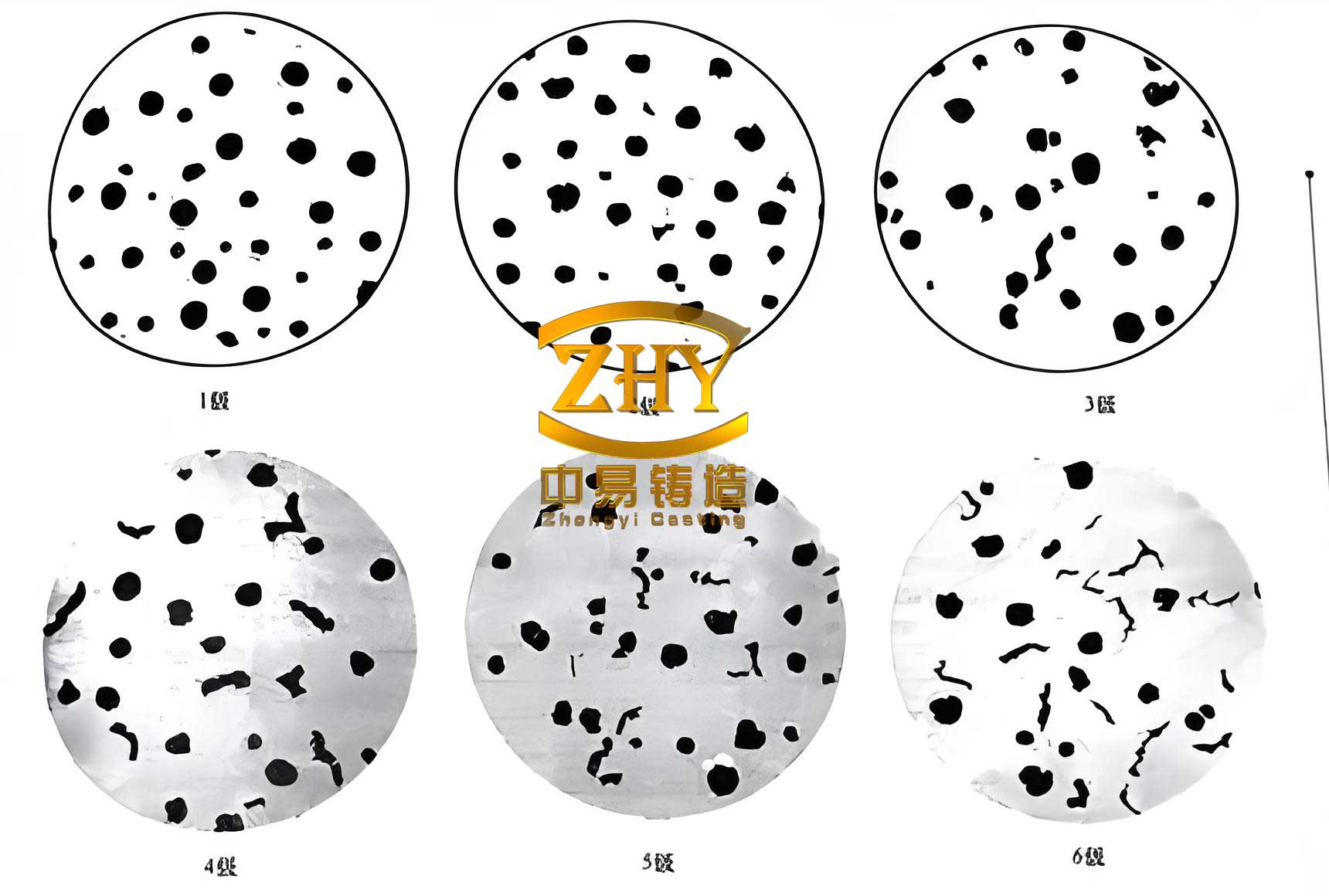
These values exceed the minimum requirements of 420 MPa tensile strength and 5% elongation, with nodularity above 80% (grade 3 or better). The microstructure predominantly consists of fine graphite nodules in a pearlitic-ferritic matrix, which is ideal for abrasive resistance in spheroidal graphite cast iron. The graphite nodule diameter, measured at 100× magnification, ranged from 4.45 to 5.21 mm, indicating effective inoculation. The successful formation of this microstructure is attributed to the controlled cooling and spheroidizing process, which is critical for spheroidal graphite cast iron components in heavy-duty applications.
Further analysis of the casting process reveals the importance of thermal management. The solidification time \(t_s\) for thick-section spheroidal graphite cast iron can be modeled using Chvorinov’s rule, modified for nodular iron:
$$t_s = k \left( \frac{V}{A} \right)^n$$
where \(V\) is volume, \(A\) is surface area, \(k\) is a constant dependent on mold material, and \(n\) is an exponent typically around 2 for sand castings. For this pump body, with a modulus \(M = V/A\) approximately 9 cm in thick zones, the use of chills reduced \(t_s\) to under 50 minutes, aligning with the goal of maintaining high nodularity. The effectiveness of the gating system can be assessed through the Reynolds number \(Re\) to ensure laminar flow:
$$Re = \frac{\rho v D}{\eta}$$
where \(v\) is flow velocity, \(D\) is hydraulic diameter, and \(\eta\) is dynamic viscosity. For spheroidal graphite cast iron at 1,340°C, \(\eta\) is roughly 0.005 Pa·s; calculations showed \(Re < 2,000\) in the ingates, indicating acceptable flow conditions. Additionally, the feeding efficiency of risers was verified using the modulus method, where the riser modulus \(M_r\) must exceed that of the casting \(M_c\):
$$M_r \geq 1.2 M_c$$
This ensured adequate feeding to counteract the shrinkage characteristic of spheroidal graphite cast iron, which has a higher shrinkage propensity than gray iron due to graphite expansion during solidification.
In conclusion, this exploration demonstrates a robust casting methodology for large, complex components in spheroidal graphite cast iron. By integrating EPS mold technology with optimized gating, chilling, risering, and advanced metallurgical treatments, we achieved a defect-free pump body meeting stringent performance criteria. The process highlights the synergy between design calculations and practical controls, such as the multi-stage inoculation for spheroidal graphite cast iron, which enhances nodule count and uniformity. Future work could focus on simulating solidification patterns using software to further refine chill placement and reduce trial runs. This case serves as a reference for producing high-integrity castings in sectors like mining and marine engineering, where spheroidal graphite cast iron offers unparalleled durability. The success underscores the importance of a holistic approach, from mold preparation to post-casting cooling, in mastering the casting of spheroidal graphite cast iron for demanding applications.