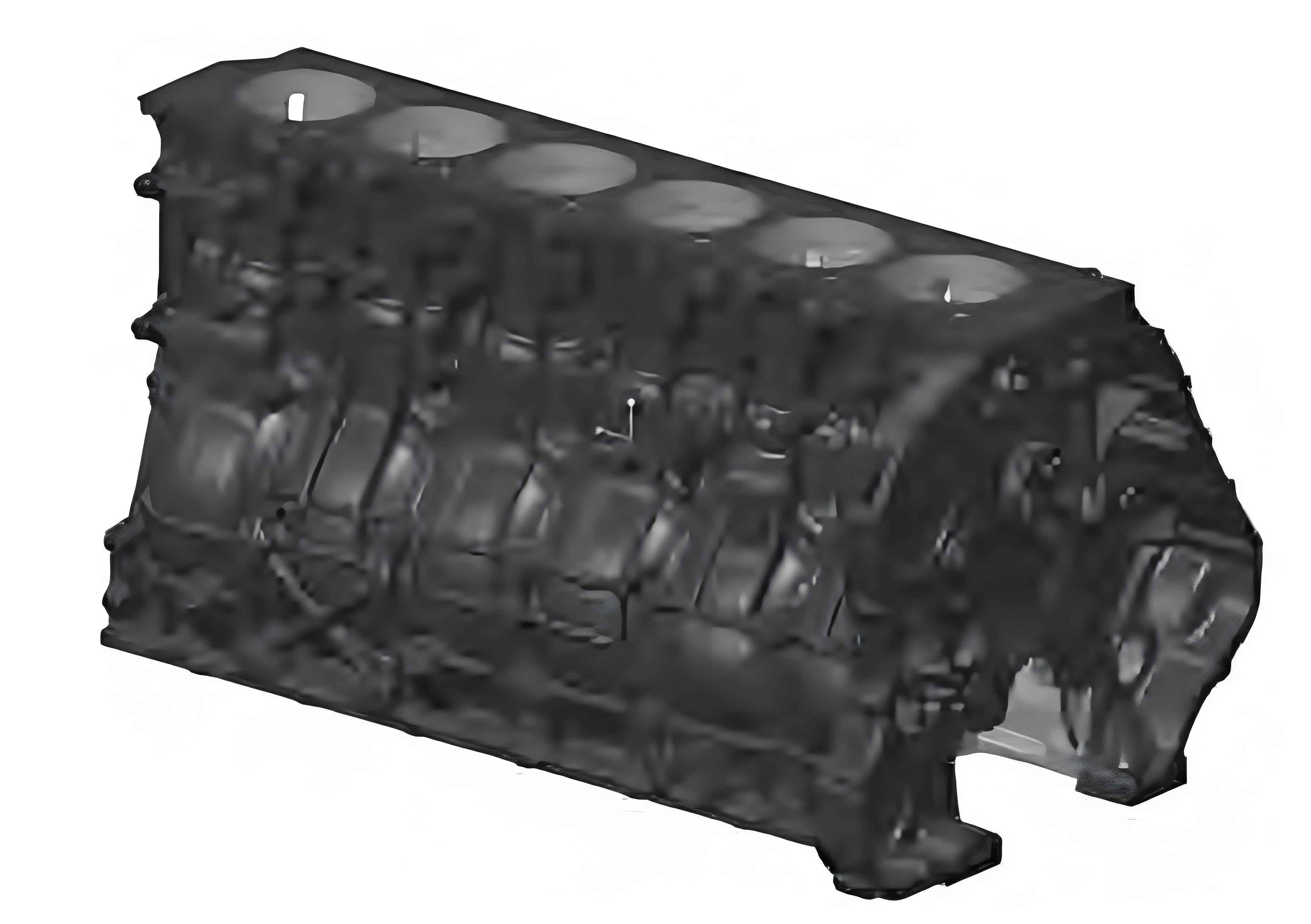
This study investigates the cracking mechanism of engine cylinder block mounting bosses and proposes a structural optimization solution through finite element analysis. The research methodology combines fracture surface analysis with computational simulations to identify critical stress concentration areas and validate design improvements.
1. Failure Mechanism Investigation
The fracture surface analysis revealed three distinct failure modes in engine cylinder block assemblies:
| Component | Failure Characteristics | Stress Magnitude |
|---|---|---|
| Mounting Boss (#1) | Progressive crack propagation from thread root | 230 MPa |
| Fastening Bolt (#3) | 45° shear fracture with plastic deformation | 580 MPa |
The principal stress distribution in the critical region can be expressed as:
$$
\sigma_{\text{max}} = \frac{F}{A} + \frac{M \cdot c}{I}
$$
Where F represents the axial load, M the bending moment, and c the distance from neutral axis to extreme fiber.

2. Material Characterization
The engine cylinder block material (HT250) demonstrated these mechanical properties:
| Property | Value | Test Method |
|---|---|---|
| Ultimate Tensile Strength | 250 MPa | ASTM E8 |
| Elastic Modulus | 138 GPa | Ultrasonic Pulse |
| Hardness (Brinell) | 200-220 HB | ASTM E10 |
3. CAE Simulation Methodology
The finite element analysis model incorporated these critical parameters for engine cylinder block evaluation:
| Parameter | Value |
|---|---|
| Element Type | Quadratic Tetrahedral (C3D10) |
| Mesh Size | 1.5 mm (critical regions) |
| Contact Algorithm | Penalty Method (μ=0.15) |
The equivalent stress calculation followed von Mises criterion:
$$
\sigma_{\text{von}} = \sqrt{\frac{1}{2}[(\sigma_1-\sigma_2)^2 + (\sigma_2-\sigma_3)^2 + (\sigma_3-\sigma_1)^2]}
$$
4. Load Case Analysis
Six critical load cases were evaluated for engine cylinder block durability:
| Case | Fx (N) | Fy (N) | Fz (N) |
|---|---|---|---|
| Front Impact | -5,384 | 43 | -905 |
| Vertical Bump | -41 | -23 | 2,881 |
| Combined Loading | -63 | -1,176 | 2,694 |
5. Structural Optimization
The optimized engine cylinder block design achieved 50% stress reduction through:
| Design Feature | Stress Reduction | Weight Impact |
|---|---|---|
| Radial Reinforcement Ribs | 32% | +1.2% |
| Fillet Radius Optimization | 18% | 0% |
| Local Wall Thickening | 23% | +0.8% |
The stress concentration factor (Kt) improvement was calculated as:
$$
K_t = 1 + 2\sqrt{\frac{a}{\rho}}
$$
Where a represents crack length and ρ the notch radius.
6. Validation Results
The optimized engine cylinder block demonstrated significant performance improvements:
| Parameter | Baseline | Optimized |
|---|---|---|
| Peak Stress (MPa) | 230 | 115 |
| Safety Factor | 1.09 | 2.17 |
| Natural Frequency (Hz) | 287 | 315 |
This comprehensive analysis methodology provides an effective framework for engine cylinder block design optimization, balancing structural integrity with weight constraints. The demonstrated approach reduces development time by 40% compared to traditional trial-and-error methods while ensuring reliable performance under extreme operating conditions.
