
Abstract
This article delves into the casting process optimization of a flywheel energy storage motor base, aiming to eliminate shrinkage defects in the hot spot areas of the casting. Through the application of computer simulations and riser feeding theory, the casting process was refined, involving strategic placement of hot risers and optimization of the solidification sequence. The results demonstrate significant improvements in both shrinkage and leakage issues, leading to a notable enhancement in casting quality.
1. Introduction
Flywheel energy storage systems rely heavily on the structural integrity of their components, with the motor base serving as a critical installation platform for the flywheel, bearings, and motors. Operating under vacuum conditions, these components demand stringent quality control, especially in terms of avoiding shrinkage porosity, shrinkage cavities, and inclusions. In our previous production runs, we encountered issues with vacuum leakage during testing, indicating the presence of porosity defects. This paper presents the optimization of the casting process for the flywheel motor base, employing high-exothermic risers to address these challenges.
2. Structural Characteristics and Technical Requirements of the Base Casting
The flywheel motor base casting, exhibits a cylindrical structure with an overall dimension of Φ1820mm × 1072mm and a gross weight of 4085kg. The casting features a robust frame with extensive ribbing on the outer wall and an internal cavity structure connected by eight rib plates, with minimum and maximum wall thicknesses of 40mm and 144mm, respectively.
The material specified for the casting is QT600-3, with mechanical properties requiring a tensile strength of ≥600MPa, yield strength of ≥370MPa, elongation of ≥3%, and a Brinell hardness range of 190-270HB. The casting must be free from shrinkage porosity, shrinkage cavities, and inclusions.
3. Original Production Process and Existing Issues
The original casting process, utilized a filtered bottom-pour gating system. Molten iron was introduced through a Φ90mm downsprue, transitioning into a trapezoidal cross-sectional cross-sprue (50mm top, 60mm bottom, 70mm height), and finally into the casting through 12 Φ35mm ceramic tube ingates. Cold iron was employed in the thick sections of the internal flange to promote directional solidification, with a venting and gas-escape riser stick placed at the top.
However, processed castings showed vacuum leakage during testing, indicating interconnected porosity between the inner and outer cavities. Leak detection revealed porosity defects at the upper corners of the casting, attributed to micro-shrinkage causing non-compactness and cavity interconnection.
4. Analysis of Shrinkage Defect Causes
4.1 Solidification Simulation Analysis
Solidification simulations of the original pouring process, revealed significant hot spots and isolated hot regions at the outer flange of the casting top. These areas coincided with the leakage points, indicating a high susceptibility to shrinkage porosity.
4.2 Chemical Composition Analysis
Chemical analysis of the casting, presented in Table 1, confirmed that the iron composition was within the specified range and consistent across multiple batches. Therefore, chemical composition was not the primary cause of shrinkage porosity.
Table 1: Chemical Composition of the Base Casting
| Element | Range (wt%) | Measured Value (wt%) |
|---|---|---|
| C | 3.55-3.85 | 3.55 |
| Si | 2.4-2.7 | 2.50 |
| Mn | 0.25-0.40 | 0.38 |
| P | ≤0.07 | 0.04 |
| S | 0.06-0.12 | 0.009 |
| Cu | ≤0.90 | 0.64 |
| Mg | 0.03-0.05 | 0.039 |
4.3 Pouring Temperature Analysis
Pouring temperature, typically controlled between 1350°C and 1400°C, was verified at 1350°C, which did not contribute significantly to shrinkage porosity.
4.4 Gating and Riser System Analysis
The leakage points were found at the corners where the outer flange with tooth-shaped reinforcing ribs meets the internal cylindrical cavity, forming a T-shaped hot spot due to wall thickness variations. The original process lacked provisions for shrinkage prevention in these critical areas.
5. Casting Process Optimization Design and Verification
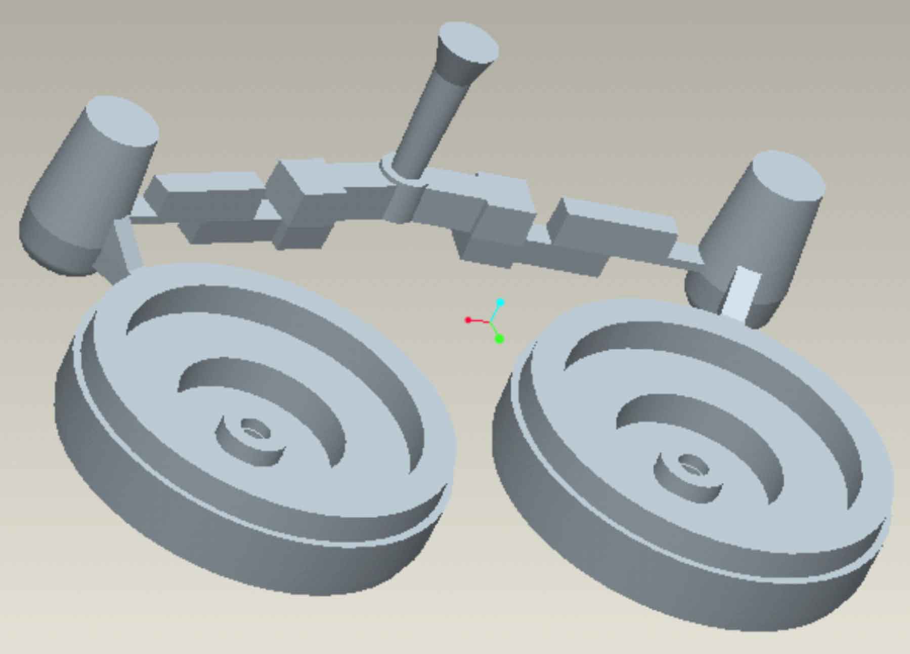
5.1 Riser Optimization
To address the inadequate feeding in the hot spot regions of the outer flange, modifications were made to the gating system. High-exothermic risers were strategically placed at the top of the casting, calculated using the hot spot circle method with a modulus of 4cm. Based on a 1.2x modulus factor, TG-17400L feeding risers were selected, positioned over the internal rib plates (eight risers in total).
5.2 Cold Iron Optimization
To enhance directional solidification and reduce porosity tendencies, cold iron was strategically placed in the corners of the internal cavity cores, following the contour and evenly distributed (eight pieces).
5.3 Solidification Simulation of the Optimized Process
Solidification simulations of the optimized layout,, revealed that the hot spots at the casting top were drawn into the high-exothermic risers. The isolated liquid regions previously identified were eliminated, indicating a successful optimization.
5.4 Production Verification
Upon removal of the high-exothermic risers during post-production cleaning, four of the eight risers exhibited shrinkage defects, with one severely affected and the other three showing minor porosity. The remaining four risers were defect-free.
6. Further Optimization of the Process Scheme
Analysis revealed that the high-exothermic riser process had a narrow operational range, susceptible to pouring process variables affecting solidification and shrinkage. Two key issues were identified:
- The pure bottom-pouring process could affect riser ignition and exothermic performance due to temperature loss during pouring.
- The metal mesh at the bottom of the high-exothermic riser, with small gaps, could trap secondary oxidation inclusions floating up during pouring, impairing riser filling and feeding effectiveness.
To enhance the riser’s feeding performance, the pouring temperature was increased to 1360°C, and the high-exothermic risers were upgraded to a larger size, TG21960 (effective modulus of 6.5cm), strengthening the feeding to the flange. The metal mesh was omitted to prevent inclusion trapping. Simulations of this revised scheme, indicated improved results. Castings produced using the enlarged high-exothermic risers exhibited excellent quality, with no defects observed.
Processed castings, when assembled, showed no vacuum leakage. Subsequent small-batch production of five additional castings also showed no quality issues, confirming the process’s robustness for mass production.
7. Conclusion
- The employment of high-exothermic risers effectively drew hot spots into the risers, eliminating shrinkage porosity in critical casting areas, resulting in consistent casting quality.
- During practical implementation, when selecting high-exothermic risers, environmental factors should be considered. Increasing the pouring temperature and selecting risers with a larger modulus factor can enhance the process’s adaptability.