
Abstract
This paper primarily delves into the various defects encountered during the casting process of a gantry structure cylinder block on an automated assembly line. Through modifications and verifications of the gating system, exhaust system, and process parameter optimizations, the casting defects were addressed, thereby satisfying the processing and assembly requirements. The paper aims to provide valuable insights and references for similar casting processes.
1. Introduction
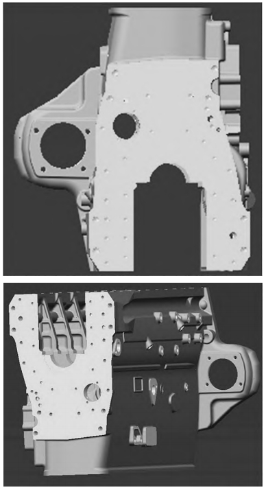
The gantry cylinder block is characterized by having the oil pan mounting plane positioned below the crankshaft’s rotational center. This design offers superior strength and rigidity, making it capable of withstanding significant mechanical loads. However, it also comes with drawbacks such as poor processability and a bulky structure. Our factory produces the 226B cylinder block, a typical example of a gantry structure.
As our factory scale expanded, the production process for the 226B cylinder block underwent significant changes, transitioning from manual core making, handling, and assembly to mass production, automation, and assembly line production. This transition, while efficient, introduced a series of casting process and processing/assembly issues. Through continuous process optimization and quality improvement, the quality of the castings has significantly improved.
This paper meticulously details the causes and mechanisms of various casting defects in this gantry cylinder block, along with the corresponding solutions implemented. It is hoped that this information can serve as a reference for other manufacturers.
2. Causes of Casting Defects and Solution Measures
During the production of this cylinder block casting, the rejection rate was relatively high. The primary defects observed included cold shuts, blowholes, damage, and sand sticking. Below, we provide an in-depth analysis of these prominent defects and the measures taken to address them.
2.1 Cold Shut Defects
The gantry design results in a large upper and lower surface for the casting, with essential locations such as the water chamber facing downwards. This orientation effectively avoids defects like blowholes, non-metallic inclusions, and broken cores. However, the upper surface, which is a large flat plane, is prone to cold shuts, especially in thin-walled areas with a wall thickness of approximately 5.5 mm.
A cold shut occurs when molten metal fails to fuse properly at the intersection during filling, resulting in penetrating or non-penetrating gaps or cavities within the casting. These defects typically have a smooth appearance, resembling the initial flow patterns of molten iron.
Cause Analysis: The cylinder block casting weighs 195 kg, with a pouring time of around 21 seconds. The cold shut defects were attributed to an unreasonably designed gating system. Specifically, the ingate was too far from the upper plane, and the gas vent distribution on the upper plane was disorganized due to the scattered positioning of bosses. Additionally, there were no ingates corresponding to the third and fifth valve seats, leading to molten iron converging from the center and two sides towards the middle positions between the second and third cylinders and the fourth and fifth cylinders. Due to the thin wall thickness, heat loss from the molten iron was rapid, causing a swift decrease in its temperature. This was particularly pronounced at the rear end, where a gear chamber was present, and insufficient molten iron replenishment occurred at the fusion point between the fourth and fifth cylinders (where two ingates met), leading to the formation of cold shuts, Blowholes also formed at positions corresponding to the third and fifth valve seats on the oil dipstick platform.
Measures Taken: additional ingates were added within the boxed area, with a cross-section of 5 mm × 25 mm. The design of the ingates corresponding to the remaining valve seats was modified to 7 mm × 20 mm, ensuring the total cross-sectional area of the ingates remained unchanged. This revised gating system improved the flow rationality of the molten iron, enhancing its fluidity and achieving better distribution of molten iron flow, which reduced the convergence of molten iron from different ingates on the large flat plane. After production verification, the improvements were found to be effective, eliminating the cold shut defects and significantly reducing the occurrence of blowholes at corresponding locations.
2.2 Blowhole Defects
Blowholes can be classified into three types based on their formation mechanism: invasion blowholes, evolution blowholes, and reaction blowholes. The blowholes in cylinder blocks are typically invasion blowholes, which result from gas emitted by sand cores and molding sand, ultimately forming bubbles that remain within the casting.
Measures Taken: Based on the causes of blowholes, the following measures were implemented:
- Controlling Residual Moisture in Sand Cores: The storage time of sand cores after exiting the drying kiln should not be too long. Only when the residual moisture content is below 0.6% is it permissible to proceed with core setting and pouring. This controls the gas emission during pouring.
- Increasing Pouring Temperature: The pouring temperature was appropriately increased from the original range of 1390–1400°C to 1410–1420°C. This enhancement improves the fluidity of molten iron on thin-walled planes and delays the formation of oxide films on the molten iron surface.
- Strictly Controlling Molding Sand Moisture: The moisture content was kept below 2.9%. While ensuring strength, the addition of bentonite was reduced to improve the permeability of the molding sand.
- Ensuring Sand Core Quality and Assembly Clearances: This prevents clogging of exhaust channels due to fire running. For thicker sand cores (such as large cylinder cores), exhaust channels are typically provided. If the sand core is not filled densely or has excessive clearances with other sand cores, molten iron may enter the exhaust channels, clogging them and preventing gas from escaping from the sand cores.
- Optimizing Riser and Gas Vent Layout: The positions of risers and gas vent pins on the upper plane of the casting corresponding to the cylinder bores were reassessed and structurally optimized. Additional venting sheets were added at the cylinder bore positions on the upper plane of the casting to facilitate the venting of gases emitted from sand cores. Irregular bosses were connected to nearby bosses with venting pins or directly.
The blowhole defects have been effectively controlled, with the defect rate dropping from the previous 5.4% to around 2%.
2.3 Damage Defects
The gantry cylinder block has a higher degree of integration compared to conventional designs. The upper and lower planes of horizontally poured cylinder block castings are relatively large, necessitating an increase in the number of risers. During the casting cleaning process on the assembly line, the increased contact area with equipment and rollers increases the risk of damage.
2.3.1 Damage Caused by Manual Operations
- Damage During Riser Removal: If the processing of the boss is not affected, it generally requires welding repair; otherwise, the casting is directly scrapped, resulting in significant waste. The measure taken was to increase the gap between the boss and the gas vent pin diameters and add a stepped structure between them, causing the fracture to occur at the junction of the two, with the stepped structure ensuring sufficient machining allowance for the boss after fracture.
- Damage During Ingate Removal: Previously, the ingate was located at the valve seat position of the cylinder block casting. Molten iron flowing through the ingate could easily cause coarse grains at that position, affecting quality and performance. Improper cleaning could also damage the valve seat. Therefore, the corresponding position of the ingate was modified from the valve seat to the side wall above the valve seat.
2.3.2 Damage Caused by Machinery
During the removal of the runner and vibratory sand removal processes, the bosses on the corresponding lower plane in contact with the equipment are prone to impact and cracking. Such damage requires adjusting the boss diameter or adding reinforcing ribs based on subsequent processing and assembly requirements to ensure the structural strength of the boss. Additionally, refining the casting cleaning operation process, establishing detailed operating standards, and providing targeted training for cleaning operators can significantly reduce cleaning damage.
3. Conclusion
The gantry cylinder block has a higher degree of integration compared to conventional designs, with relatively large upper and lower planes of horizontally poured castings, making it prone to defects such as cold shuts, misruns, shrinkage porosity, and blowholes. During casting cleaning on the assembly line, the risk of human and mechanical damage increases. This paper primarily introduced the cold shut, blowhole, and damage defects encountered and the corresponding improvement measures, hoping to provide a reference for similar casting processes.
By meticulously analyzing the causes of casting defects and implementing targeted solutions, the quality of the gantry cylinder block castings has been significantly improved. These improvements not only enhance the performance and reliability of the cylinder block but also contribute to improving production efficiency and reducing costs, ultimately enhancing the competitiveness of the product in the market.