
The relentless pursuit of higher efficiency, lower emissions, and reduced weight in internal combustion engines drives continuous innovation in core component design. As a result, modern cylinder blocks have evolved into highly integrated, structurally complex castings, consolidating functions like water jackets, oil galleries, and gear housings into a single unit. This integration presents significant challenges for foundry engineering, demanding unparalleled precision in core assembly, robustness in core sand properties, and meticulous control over mold filling and solidification. The transition towards these intricate designs often exposes the limitations of traditional casting methodologies.
This article details a comprehensive investigation and resolution of severe gas defect issues encountered during the initial trial production of a new-generation 4-cylinder dry-liner cylinder block. Adopting a first-person engineering perspective, I will systematically walk through the structural analysis, initial process design, root cause investigation, and the multi-faceted optimization strategy that ultimately led to a successful, robust manufacturing process. The principles discussed, while centered on a gray iron application, are fundamental to casting quality and are equally critical when working with materials like nodular cast iron, where shrinkage behavior differs but gas formation mechanisms remain a paramount concern.
Part 1: Casting Product Analysis and Initial Process Design
The subject component is a cylinder block cast in Grade HT300 gray iron. Key specifications are summarized below:
| Parameter | Specification |
|---|---|
| Material | HT300 Gray Iron |
| Weight (approx.) | 190 kg |
| Dimensions (LxWxH) | 516 mm x 551 mm x 432 mm |
| Nominal Wall Thickness | 6 mm |
| Tensile Strength (Boss Requirement) | >250 MPa at 18 specified locations |
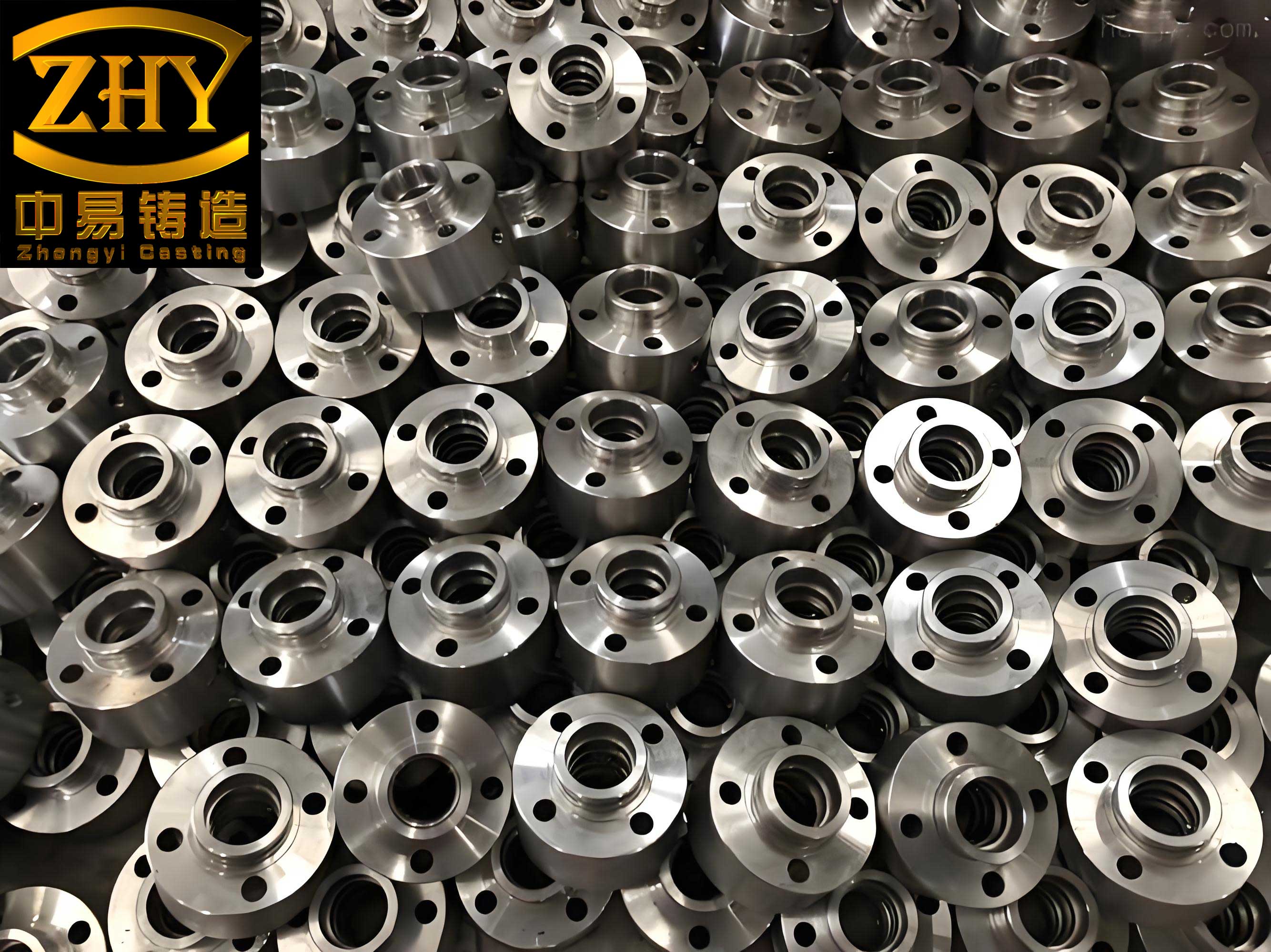
The block’s complexity is immediately apparent. It features thin, uniform walls, a deep crankcase, and an integrated gear housing projecting 180 mm from the rear face. This gear housing represents a significant thermal mass, prone to mistuns and shrinkage-related defects. Furthermore, the internal core package is exceptionally complex. The oil and gas transfer passages form intersecting, curved channels on the block’s side. During pouring, these cores experience substantial buoyancy forces, risking deformation or fracture. The water jacket core, connected to narrow horizontal water channels, must exhibit exceptional resistance to sintering and veining to ensure clean internal passages post-cast and avoid costly rework.
The initial manufacturing process was designed based on established practices for similar blocks. It utilized high-pressure green sand molding on an HWS molding line with flask dimensions of 1000 mm x 800 mm x 350/350 mm (cope/drag). The casting was oriented horizontally (flat-back), with the heavy gear housing placed in the drag to minimize the risk of mistun at its highest point.
The internal cavity was formed by an assembly of 11 separate cores, detailed in the table below:
| Core # | Description | Core Sand Process | Coating Strategy |
|---|---|---|---|
| #1-#6 | Main Side Cores (Crankcase) | Cold Box (Phenolic Urethane) | Assembled & dipped as a unit |
| #7 | Bulkhead Core (Rear face) | Cold Box (Phenolic Urethane) | Individual coating |
| #8 | Water Jacket & Passage | Shell (Hot Box) | Individual coating |
| #9, #11 | Oil/Gas Gallery & Channels | Shell (Hot Box) in a frame | Individual coating |
| #10 | Tappet Chamber Core | Furan No-Bake | Individual coating |
To manage this complexity, a strict process flow was established: the main side cores were assembled and dipped as a unit, then stored vertically. Other cores were individually coated and dried before being assembled onto the main core package. A dedicated fixture with pneumatic actuators was used to rotate the entire assembly 90 degrees and lower it precisely into the drag mold.
The gating system was a conventional pressurized (choke-at-bottom) design with a ratio intended to promote a smooth fill: ΣFsprue : ΣFrunner : ΣFingate = 1.1 : 1.4 : 1. Ingates were positioned to avoid direct impingement on the critical main bearing cap areas. Multiple overflow and round pencil vents were placed on the top (cope) face and ends of the casting. The total vent area was designed to be 1.7 times the total ingate area. The pouring temperature was controlled between 1400 – 1430°C.
Part 2: Problem Identification and Root Cause Analysis
The first trial batch of five castings resulted in a 100% scrap rate due to gross gas defects. The defects manifested as large, isolated subsurface blowholes primarily located on raised bosses, strengthening ribs, and areas directly above the complex oil gallery cores on the cope surface. The venting system had clearly failed: pencil vents were short, incomplete, or hollow, indicating severe back-pressure within the mold cavity during pouring.
Upon sectioning, the defect morphology confirmed the diagnosis. The cavities were smooth-walled, often with a bluish or oxidized tint, classic indicators of invasive gas defects. This occurs when gas generated from the sand cores (binders, moisture) during metal pouring cannot escape quickly enough and is forced into the solidifying metal.
A comparative analysis with previous, less complex block designs pinpointed the root cause: Increased Gas Generation coupled with Inadequate Gas Evacuation.
- Gas Load Increase: The new integrated oil/gas gallery added an entire extra layer of large, thick core sections. The total volume of resin-bonded sand increased significantly. The gas generation potential of the core assembly can be conceptually modeled as proportional to the core mass and its specific gas evolution rate:
$$ G_{total} = \sum_{i=1}^{n} (m_{core,i} \cdot g_{sand,i}) $$
Where \( G_{total} \) is the total gas potential, \( m_{core,i} \) is the mass of core \( i \), and \( g_{sand,i} \) is its specific gas evolution value. For the new design, \( G_{total}^{new} \approx 2.08 \times G_{total}^{old} \). - Exhaust Capacity Deficiency: While vent area was increased, it was insufficient for the new gas load. More critically, the排气 paths from the deep, interconnected cores to the mold periphery were likely obstructed or too long. The排气 efficiency \( \eta_{vent} \) can be thought of as a function of vent area \( A_v \), permeability \( k \), and path length \( L \):
$$ \eta_{vent} \propto \frac{A_v \cdot k}{L} $$
In the initial design, for the new core package, the effective path length \( L \) increased while \( A_v \) did not scale adequately, leading to \( \eta_{vent} \) dropping below the critical threshold.
Part 3: A Systemic Optimization Strategy
The solution required a three-pronged attack targeting the core sand system, the gating/venting system, and minor product design collaboration.
3.1 Core Sand &排气 System Redesign
The focus was on reducing gas generation and maximizing排气 velocity from the core package itself.
| Optimization Action | Technical Rationale & Impact |
|---|---|
| 1. Oil Gallery Core Sand Change: Replaced 50/100 mesh silica shell sand with 40/70 mesh “Baozhu” (ceramic) sand. | Spherical “Baozhu” sand offers higher permeability, allowing lower binder content (reducing \( g_{sand} \) from ~15.6 mL/g to ~10.2 mL/g). The larger grain size and shape further enhance intrinsic permeability \( k \), accelerating gas diffusion out of the core. |
2. Integrated Core Vents & Seals:
|
Creates dedicated, low-resistance排气 channels (\( \downarrow L \)) from the core interior directly to the external mold. The asbestos gasket acts as a “fire seal,” preventing metal penetration that would block these vital passages while still allowing gas flow. |
| 3. Enhanced Water Jacket Core排气: Added explicit vent holes at the interface between the water jacket core and the main side cores. | Prevents gas trapping in the upper sections of the water jacket core, another potential source for cope-side defects. |
3.2 Gating and Mold排气 Optimization
The goal was to improve thermal gradient and provide more, faster escape routes for gas.
| Optimization Action | Technical Rationale & Impact |
|---|---|
| 1. Gating System Revision: Changed to a more open ratio: ΣFsprue : ΣFrunner : ΣFingate = 1.5 : 2 : 1. Added small top ingates. | A less pressurized system promotes a quiescent fill, reducing turbulence and air entrainment. Top ingates help keep the metal temperature high in the cope section, delaying solidification and allowing more time for gas to escape from the metal (\( \uparrow \text{Time}_{available} \)). |
| 2. Filter Upgrade: Replaced 2 pcs of 60x60x16 mm ceramic filters with 2 pcs of 70x70x16 mm filters, oriented vertically. | Increased filter open area by 44% (\( \uparrow A_{filter} \)). Vertical orientation minimizes dross accumulation on the filter face, maintaining a higher flow rate and reducing pour time (\( \downarrow t_{pour} \)), which lowers total gas generation exposure time. |
| 3. Aggressive Mold排气: Added numerous vent pins in the parting line, overflow vents at the highest points of the drag-side flange, and increased exhaust drilling count from 25 to 37 locations. | Dramatically increased the total vent area \( A_v \) by approximately 48%. Overflow vents on the drag draw off cooler, potentially gas-laden first metal, further improving the quality of metal rising into the cope. |
3.3 Product Design Collaboration
In consultation with product engineers, two 20mm wide strengthening ribs were added to the highest, non-functional arcs of the oil gallery exterior wall. This provided an ideal location for placing substantial pencil vents directly above the most problematic core area, effectively increasing \( A_v \) at the most critical location.
Part 4: Results and Validation
The optimized process was validated over three production batches totaling 45 castings. The results were conclusive:
- Defect Elimination: The severe gas defects on the cope surface were completely eliminated.
- Yield Improvement: The casting yield (good castings from mold) exceeded 95%.
- Machining Verification: Subsequent machining of all cope-side bosses and features confirmed the absence of subsurface blowholes.
The successful resolution validated the systemic approach: reducing core gas generation, engineering positive排气 paths from within the core package, and optimizing the mold’s thermal and排气 dynamics.
Part 5: In-Depth Technical Discussion and Material Considerations
The challenge faced here underscores a universal principle in casting: managing the gas balance within the mold cavity. The equation is deceptively simple: Gas In (from sand, coatings, turbulence) must be less than Gas Out (through vents, permeable sand) for the entire duration of filling and initial solidification. This case study excelled in manipulating all variables in that equation.
An important extension of this discussion involves material selection. While this specific block used gray iron, the automotive industry is increasingly exploring nodular cast iron (ductile iron) for high-performance or weight-critical blocks. Nodular cast iron offers superior tensile strength, ductility, and fatigue resistance compared to gray iron. However, its casting behavior presents different challenges. The magnesium treatment used to spheroidize the graphite creates a greater tendency for dross formation (magnesium oxides/sulfides) and can slightly increase the melt’s susceptibility to gas pickup, particularly hydrogen.
Therefore, the lessons on pristine core sand practice, optimized gating for minimal turbulence, and flawless排气 become even more critical when casting nodular cast iron components. Any invasive gas defect in a nodular cast iron casting is not just a surface quality issue but a severe stress concentrator that can drastically reduce the component’s fatigue life, nullifying the material’s advantages. The filtration system optimization described would be non-negotiable for nodular cast iron to control dross.
Furthermore, the solidification characteristics differ. Gray iron solidifies with graphite expansion offsetting shrinkage, allowing simpler feeding. Nodular cast iron experiences a significant post-inoculation contraction (shrinkage) and requires careful application of risers (feeders) to ensure soundness, especially in heavy sections like the gear housing or bulkheads. The feeding demand \( V_{feed} \) for a nodular cast iron section can be estimated as:
$$ V_{feed} \approx \beta \cdot V_{casting} $$
where \( \beta \) is the volumetric shrinkage factor (typically 4-6% for nodular cast iron, versus ~1% for gray iron). This necessitates a fundamentally different approach to rigging design for feeding versus the primarily排气-focused strategy used here for gray iron. A hybrid block design might use nodular cast iron in high-stress areas (main bearing caps, deck) and gray iron elsewhere, complicating the process further.
The image above illustrates the distinctive microstructure of nodular cast iron, characterized by spherical graphite nodules embedded in a metallic matrix. Achieving this structure consistently in complex, thin-walled castings like a cylinder block requires exquisite control over melt chemistry, cooling rates, and mold dynamics—the very factors governed by the type of optimized casting process detailed in this article.
In conclusion, the development of the new-generation cylinder block casting process was an exercise in systematic problem-solving. It moved beyond simple trial-and-error to a diagnostic approach based on quantifying gas generation and排气 efficiency. The solutions—spanning sand technology, core engineering, gating physics, and collaborative design—created a robust process. This methodological framework is directly transferable to the production of even more demanding components, including those made from advanced materials like nodular cast iron. The core tenets remain: minimize gas sources, maximize and safeguard排气 pathways, and control thermal gradients. As casting geometries evolve towards greater integration and complexity, this holistic view of the mold cavity as a dynamic system is essential for achieving high-quality, reliable components.