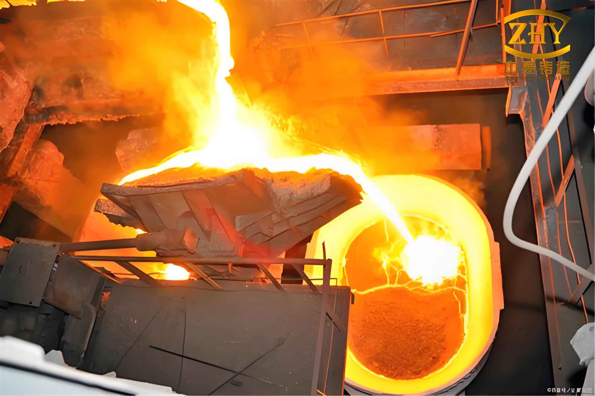
In the development of new automotive products, rapid prototyping of complex aluminum alloy castings is a critical step for design validation and performance testing. Traditional metal die casting, while suitable for mass production, incurs high tooling costs and long lead times that are prohibitive for trial manufacturing. To address this challenge, we integrated additive manufacturing of wax patterns with plaster mold investment casting to produce a manual transmission housing. This paper details our technical approach, key process parameters, dimensional accuracy analysis, and application outcomes, demonstrating that the combination of 3D printing and high precision investment casting offers a reliable, cost‑effective, and agile solution for small‑batch production of complex aluminum alloy components.
The transmission housing is a core component of the vehicle powertrain, requiring excellent dimensional accuracy, leak tightness, and mechanical strength. The original design was intended for high‑pressure die casting using ADC12 alloy. For prototype trials, we needed to achieve equivalent mechanical properties using a different alloy (ZL101A) while maintaining casting precision at CT5 level. The 3D‑printed wax pattern – plaster mold – vacuum‑assisted casting process chain was selected based on its ability to produce near‑net‑shape castings without any hard tooling. The entire workflow from CAD model to finished casting took only 21 days for a batch of 10 pieces, reducing lead time by more than 50% compared to conventional die casting mold fabrication.
Technical Route and Process Overview
The overall technical route is illustrated schematically as follows: starting from a 3D CAD model of the transmission housing, the model is converted to STL format for selective laser sintering (SLS) printing. The printed green part is infiltrated with wax to produce a robust wax pattern. This pattern is then invested with a plaster slurry, dried, dewaxed, and fired to create a permeable ceramic mold. Finally, molten aluminum alloy (ZL101A) is cast under vacuum and subsequent pressurization. The key process steps are:
| Process Step | Description | Key Parameters |
|---|---|---|
| SLS Wax Pattern | Laser sintering of polymer powder (PSB) followed by wax infiltration | Build volume 500×500×450 mm; laser power 31 W; chamber temperature 110 °C; layer thickness 0.15 mm; total layers 1,074 |
| Plaster Mold Making | Slurry prepared with α/β hemihydrate gypsum, refractory fillers, and additives; poured around wax pattern; dried naturally | Gypsum 30–50 %; fillers (quartz, kaolin, bauxite) 50–70 %; additives <5 %; water/powder ratio 50–80 % at 30–40 °C |
| Dewaxing & Firing | Gradual ramp heating to burn out wax and sinter plaster mold | Multi‑stage ramp with hold periods; peak temperature typically 700–800 °C; controlled atmosphere to remove residues |
| Vacuum‑Pressure Casting | Mold placed in vacuum chamber (<1 kPa); alloy poured under vacuum; then pressurized to 0.6 MPa during solidification | Vacuum level <1 kPa; pressurization 0.6 MPa; alloy pouring temperature 720–740 °C |
| Finishing & Inspection | Removal of plaster by water jet; heat treatment (T6); CNC machining of critical features; dimensional and mechanical validation | T6: solution treatment at 535 °C for 8 h, water quench, artificial aging at 175 °C for 6 h |
This process chain fully exploits the synergy between additive manufacturing and high precision investment casting. The wax pattern produced by SLS exhibits strength comparable to injection‑molded wax, while the plaster mold offers excellent surface replication and low cost for small batches.
Key Process Design Aspects for High Precision Investment Casting
SLS Wax Pattern Fabrication
We used the AFS500 SLS system with PSB polymer powder and a post‑infiltration of paraffin wax. The powder layer thickness was set to 0.15 mm, and the laser scanning strategy was optimized to minimize distortion. The total printing time for the transmission housing (approx. 9.6 kg final casting) was about 12 hours. The wax pattern after infiltration exhibited a tensile strength of about 5 MPa, sufficient for handling and plaster investment. Dimensional accuracy of the SLS wax pattern directly influences the final casting precision. We measured the deviation between the scanned point cloud of the wax pattern and the nominal CAD model (including a uniform shrinkage allowance of 1.5 % for ZL101A). The statistical analysis gave a standard deviation $$\sigma = 0.5468\ \text{mm}$$, with 98.89 % of measurement points within ±3σ. This deviation is acceptable for CT5‑grade castings.
Plaster Mold Formulation and Thermal Cycle
The plaster slurry composition was optimized to achieve a balance between green strength, permeability, and collapsibility. The basic formulation is given in the table above. The water temperature was maintained at 35 °C to control setting time. After pouring, the mold was allowed to set for 2 h, then naturally dried for 24 h before dewaxing. The firing schedule involved a slow ramp (50 °C/h) up to 300 °C with a dwell of 2 h to remove moisture, followed by a higher ramp to 750 °C with a 2‑hour soak to fully burn out residual wax and sinter the plaster. The firing curve can be represented as:
$$T(t) =
\begin{cases}
20 + 50t, & 0 \le t < 5.6\ \text{h} \\
300, & 5.6 \le t < 7.6\ \text{h} \\
300 + 100(t-7.6), & 7.6 \le t < 12.1\ \text{h} \\
750, & 12.1 \le t < 14.1\ \text{h}
\end{cases}$$
where $$T$$ is temperature in °C and $$t$$ is time in hours. This schedule prevented cracking due to rapid moisture evaporation and ensured complete wax removal, which is critical for high precision investment casting.
Vacuum‑Pressure Casting Technique
To fill thin‑walled sections (minimum wall thickness 2.5 mm) and to eliminate porosity, we employed a combination of vacuum pouring and pressure solidification. The plaster mold, still hot from firing (about 400 °C), was placed in the vacuum chamber. After evacuation below 1 kPa, molten ZL101A at 730 °C was poured through a bottom‑gating system. Immediately after pouring, the chamber was pressurized with dry air to 0.6 MPa and held until complete solidification. This process enhances the feeding capability and reduces micro‑shrinkage, resulting in a dense structure. The mechanical properties after T6 heat treatment were measured as: ultimate tensile strength 275 MPa, elongation 2 %, and hardness 85 HBS, exceeding the die‑cast ADC12 baseline (228 MPa, 1.4 %, 74 HBS). The process parameters for the vacuum‑pressure cycle are summarized below:
| Parameter | Value |
|---|---|
| Mold temperature at pouring | 400 °C |
| Alloy pouring temperature | 730 °C |
| Vacuum level before pouring | <1 kPa |
| Applied pressure during solidification | 0.6 MPa |
| Pressure holding time | 5 min after complete filling |
This vacuum‑pressure casting technique is a key enabler for high precision investment casting of complex, thin‑walled castings, as it ensures both faithful mold filling and sound internal quality.
Dimensional Accuracy Analysis
Wax Pattern Accuracy
The 3D‑printed wax pattern was digitized using an ATOS‑CS‑2M structured‑light scanner with an accuracy of ±0.02 mm. The point cloud was registered to the nominal CAD model (including 1.5 % shrinkage compensation) in Geomagic Control software. The deviation histogram is approximately Gaussian, with a mean offset of 0.08 mm and a standard deviation of 0.5468 mm. The fact that 98.89 % of points lie within ±3σ confirms that systematic errors (e.g., scaling, warpage) are well controlled. The main sources of deviation are:
- STL tessellation error (controlled to <0.1 mm)
- Layer‑wise staircase effect (layer thickness 0.15 mm)
- Thermal shrinkage and post‑cure distortion of the polymer/wax composite
To quantify the effect of these errors on the final casting, we developed a simple error propagation model. Let $$E_w$$ be the wax pattern deviation (standard deviation $$\sigma_w = 0.55\ \text{mm}$$). The plaster mold replication error $$E_m$$ is typically small ($$\sigma_m \approx 0.1\ \text{mm}$$) due to the fluidity of the slurry. During dewaxing and firing, additional distortion $$E_f$$ occurs, estimated at $$\sigma_f = 0.2\ \text{mm}$$. The casting solidification shrinkage $$E_s$$ for ZL101A is about 1.3 % linear, but is compensated in the original model. The total casting deviation $$\sigma_c$$ is approximately:
$$\sigma_c = \sqrt{\sigma_w^2 + \sigma_m^2 + \sigma_f^2} \approx \sqrt{0.55^2 + 0.1^2 + 0.2^2} = 0.597\ \text{mm}$$
This predicted value agrees well with the measured casting standard deviation of 0.483 mm, indicating that the wax pattern is the dominant contributor. The slightly lower measured value suggests some error cancellation in the actual process.
Casting Accuracy
The final transmission housing casting was scanned and compared to the nominal geometry. The results are summarized in the following table:
| Measurement Feature | Nominal Dimension (mm) | Measured Dimension (mm) | Deviation (mm) |
|---|---|---|---|
| Center distance (Shaft A – B) | 78.0 | 78.4 | +0.4 |
| Center distance (Shaft A – C) | 85.0 | 84.5 | −0.5 |
| Center distance (Shaft A – D) | 193.15 | 193.8 | +0.65 |
| Distance (Flange G – H) | 141.0 | 141.8 | +0.8 |
| Distance (Shaft A – Boss E) | 151.0 | 151.6 | +0.6 |
| Distance (Shaft A – Boss F) | 185.0 | 185.8 | +0.8 |
All measured deviations are within ±0.8 mm, which satisfies the CT5 tolerance range for this casting size (CT5 typical tolerance for 100–200 mm is about ±0.5 mm to ±0.9 mm). The overall casting standard deviation was 0.483 mm, with 97.34 % of surface points within ±3σ. This level of precision demonstrates that the combination of 3D printing and plaster mold high precision investment casting can consistently achieve CT5 grade without the need for hard tooling modifications.
Application Results and Benefits
Ten transmission housing castings were produced using the developed process. After T6 heat treatment and CNC machining of critical bearing seats and flange surfaces, all parts passed dimensional inspection and were assembled into prototype gearboxes. The castings exhibited excellent leak tightness (no porosity defects detected by dye penetrant testing) and withstood the required torque of 310 Nm during bench testing. The main advantages observed for this integrated approach are:
- Reduced lead time: 21 days from CAD to finished casting vs. about 3 months for die casting mold fabrication.
- Lower cost for low volumes: Approximately ¥8,000 per piece for the prototype batch, compared to hundreds of thousands of yuan for a permanent mold.
- Design flexibility: Any modifications to the housing geometry can be implemented by simply updating the STL file and reprinting the wax pattern, with no additional tooling cost.
- High material performance: The ZL101A-T6 casting exceeded the mechanical properties of the original ADC12 die‑cast specification, providing better ductility and strength.
The process chain we developed is not limited to transmission housings. It can be applied to any complex aluminum or other non‑ferrous alloy casting where rapid prototyping and small‑batch production are required. The key is to carefully manage shrinkage compensation in the wax pattern design and to optimize the plaster mold firing cycle for the specific geometry. In our practice, high precision investment casting through 3D printing has become a routine method for new product development.
Conclusion
We have successfully demonstrated that integrating SLS 3D‑printed wax patterns with plaster mold vacuum‑pressure casting yields an efficient, low‑cost, and precise process for manufacturing aluminum alloy transmission housings. The dimensional accuracy of the final castings meets CT5 grade, and the mechanical properties satisfy prototype testing requirements. The entire workflow is agile and adaptable, making it ideal for high precision investment casting of complex components in small series. This technology bridges the gap between rapid prototyping and functional casting, enabling faster product development cycles in the automotive and aerospace industries.