
In my extensive experience with water supply pipeline engineering, I have consistently observed the widespread adoption of nodular cast iron pipes due to their exceptional properties, such as rapid installation, superior sealing performance, and long service life. These pipes are integral to modern infrastructure, particularly in long-distance water transmission systems. However, segmented construction is often necessitated by factors like tight deadlines, work zone divisions, land acquisition progress, building distributions, and directional drilling crossings. To connect these segmented nodular cast iron pipelines into a continuous whole, T-type socket fittings are employed. These fittings, made from the same high-quality nodular cast iron as the pipes themselves, serve as crucial coupling components. Traditionally, installing these fittings has been labor-intensive, time-consuming, and prone to quality issues, including potential leakage from disturbing already-installed pipes. Motivated by these challenges, I have dedicated efforts to developing and refining a rapid installation technique that leverages specialized tools, ensuring efficiency, reliability, and cost-effectiveness. This article delves into this innovative method, emphasizing the material advantages of nodular cast iron and presenting detailed analyses through tables and formulas to summarize key concepts.
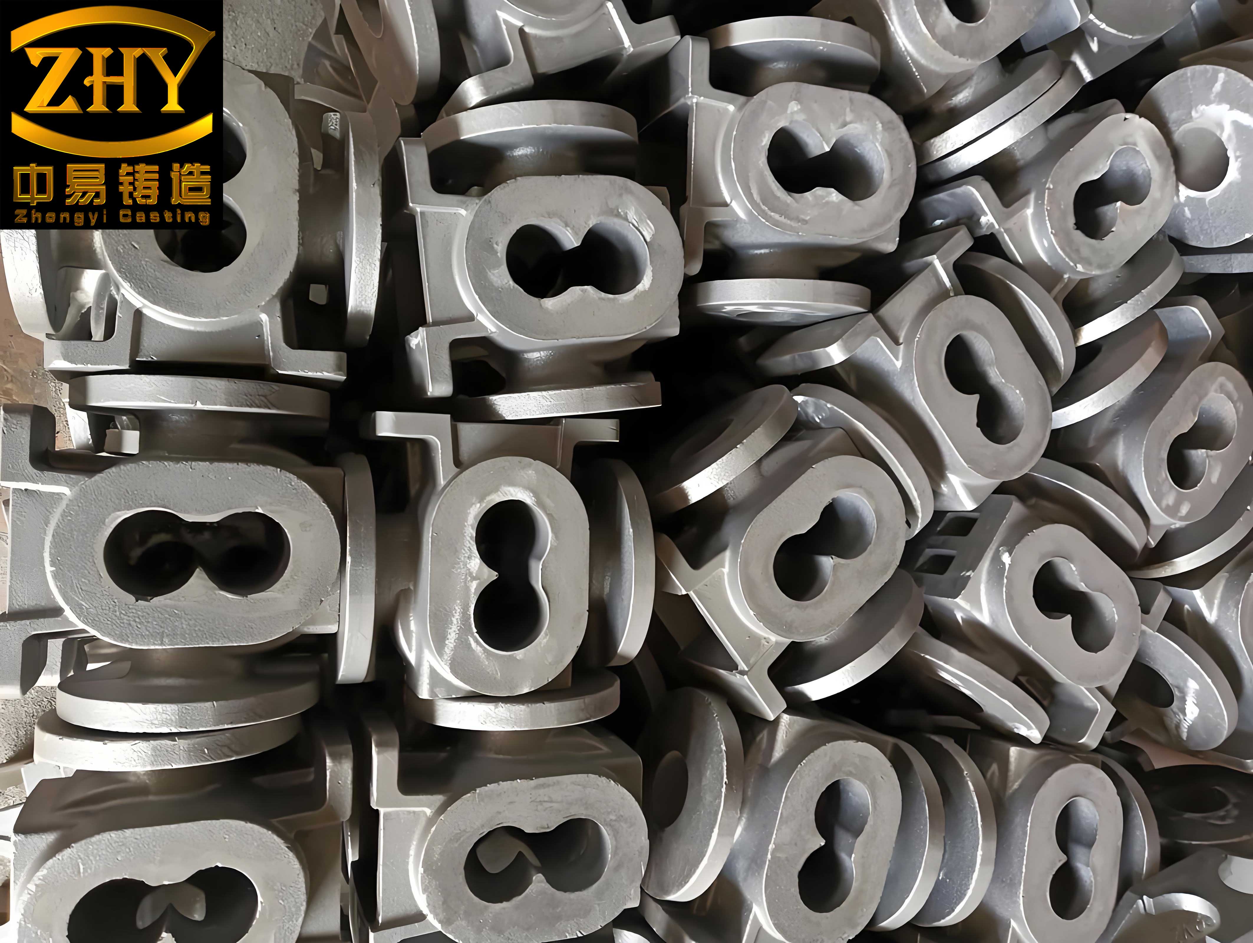
The T-type socket fitting for nodular cast iron pipes is a double-socket coupling, typically 50 cm in length, with socket ends each having a edge thickness of approximately 6.2 cm. It is designed to join two disconnected spigot-and-socket type pipelines. Available in various diameters such as DN600, DN700, and DN1200, it matches the pipe dimensions to maintain system integrity. The primary function is to facilitate pipeline closure or “making-up” during segmented construction, ultimately achieving a fully integrated pipeline network. The inherent strength and ductility of nodular cast iron make these fittings durable under operational stresses.
Conventional installation methods for T-type socket fittings involve cleaning the socket interiors, installing sealing gaskets (often rubber rings) in a cross or star pattern, applying lubricants like edible oil to reduce friction, and using chain blocks or pullers. Specifically, two chain blocks are symmetrically fixed on either side of the pipeline—one end anchored to the already-installed pipe and the other to the T-type socket fitting. Simultaneous and even force is applied to pull the socket onto the spigot until it reaches the installation mark. While seemingly straightforward, this approach presents several significant drawbacks that compromise project timelines and quality.
Firstly, the frictional resistance during installation is substantial. Since both ends of the T-type socket fitting are equipped with sealing gaskets, pulling the fitting directly onto the pipe requires overcoming double the friction compared to a standard socket connection. The force required, \( F_{\text{pull}} \), can be approximated by the formula for frictional force:
$$F_{\text{pull}} = 2 \times \mu \times N$$
where \( \mu \) is the coefficient of friction between the gasket and pipe (typically ranging from 0.1 to 0.3 for lubricated rubber on nodular cast iron), and \( N \) is the normal force exerted by the gasket compression. For a DN700 nodular cast iron pipe, the contact pressure from gasket compression might average \( P = 0.5 \, \text{MPa} \), with a contact area \( A \) per gasket of approximately \( 0.1 \, \text{m}^2 \). Thus, the normal force per gasket is \( N = P \times A = 0.5 \times 10^6 \, \text{Pa} \times 0.1 \, \text{m}^2 = 50,000 \, \text{N} \). With two gaskets and \( \mu = 0.2 \), the pulling force becomes:
$$F_{\text{pull}} = 2 \times 0.2 \times 50,000 = 20,000 \, \text{N} \approx 2.04 \, \text{metric tons force}$$
This necessitates heavy-duty chain blocks, often exceeding 5 tons capacity, which are cumbersome and require significant manual effort.
Secondly, the compact size of the T-type socket fitting (only 50 cm long) makes it difficult to secure firmly. Installation straps or slings tend to slip during pulling, leading to repeated adjustments and prolonged installation times. This inefficiency is exacerbated in field conditions where precision is critical.
Thirdly, and most critically, the conventional method risks disturbing previously installed pipelines. The pulling force exerted on the T-type socket fitting is transmitted to the anchored pipes, which may not have sufficient inherent stability to resist movement. To mitigate this, external stabilization methods like soil backfilling or bracing are employed, but these are not always reliable. If the upstream or downstream pipe joints are displaced or loosened during installation, sealing integrity is compromised, leading to potential leaks. This undermines the very advantage of nodular cast iron pipes—their reliable, long-term performance.
| Issue | Description | Impact |
|---|---|---|
| High Frictional Resistance | Double gasket contact doubles pulling force, requiring heavier equipment. | Increased labor, time, and equipment costs. |
| Fitting Fixation Difficulty | Small fitting size leads to strap slippage and instability. | Prolonged installation time and safety risks. |
| Pipeline Disturbance Risk | Pulling forces can displace anchored pipes, compromising joint integrity. | Potential leaks, reduced quality, and need for rework. |
To address these challenges, I have developed a rapid installation toolkit and methodology centered on a circumferential clamping system and hydraulic jacks. This approach minimizes direct pulling on the pipeline, thereby preserving stability and enhancing efficiency. The core components include specially designed circumferential clamps (hoop straps), hydraulic jacks, high-strength bolts, and rubber padding. All elements are engineered to work seamlessly with nodular cast iron pipes, leveraging their material properties.
The circumferential clamp is fabricated from 15 mm thick steel plates, 30 cm wide, formed into two semi-circular arcs that match the external diameter of the nodular cast iron pipe. Each semi-arc features reinforced end plates with bolt holes and is strengthened with steel gussets to withstand high loads. A central thrust platform, welded onto each semi-arc, provides a stable base for the hydraulic jack. The clamp is secured around the pipe using high-strength bolts through the end plates, ensuring a tight grip without damaging the nodular cast iron surface. To prevent slippage and protect the pipe’s coating, a 3 mm thick rubber pad is affixed to the inner surface of the clamp. The design ensures uniform pressure distribution, which is crucial for maintaining the structural integrity of the nodular cast iron pipe during installation.
The hydraulic jacks are selected based on pipe diameter and the required thrust force. For instance, for a DN700 nodular cast iron pipe, the weight of the T-type socket fitting and the frictional resistance necessitate jacks with a capacity of at least 10 metric tons each. Typically, two jacks are used symmetrically to apply even force. The thrust force required to push the T-type socket fitting off a short pipe section and onto the main pipeline can be calculated similarly to the pulling force, but with the advantage of controlled application. The force \( F_{\text{push}} \) is given by:
$$F_{\text{push}} = \mu \times N \times n$$
where \( n \) is the number of gasket interfaces being traversed simultaneously. In the rapid method, initially only one gasket interface is engaged when pushing the fitting off the short pipe, so \( n = 1 \). Using the same parameters as before:
$$F_{\text{push}} = 0.2 \times 50,000 = 10,000 \, \text{N} \approx 1.02 \, \text{metric tons force}$$
Thus, a 10-ton jack provides a safety factor of nearly 10, ensuring smooth operation. This calculated approach underscores the efficiency gains when using nodular cast iron components, as their consistent material properties allow precise force estimations.
| Component | Specifications | Function |
|---|---|---|
| Circumferential Clamp (Hoop Strap) | 15 mm thick steel, 30 cm wide, semi-circular arcs with thrust platform and rubber padding. | Provides secure anchorage on pipe for jack reaction force. |
| Hydraulic Jack | Minimum 10-ton capacity for DN700 pipe; scalable based on pipe diameter. | Generates controlled thrust to move T-type socket fitting. |
| High-Strength Bolts | Grade 8.8 or higher, with nuts and washers. | Secures clamp halves around nodular cast iron pipe. |
| Rubber Padding | 3 mm thickness, high-friction material. | Prevents clamp slippage and protects pipe coating. |
The rapid installation process follows a systematic sequence to ensure accuracy and quality. It involves measurement, cutting, gasket installation, T-type socket fitting pre-assembly, short pipe installation, and final closure using the jacking system. Each step is designed to minimize human error and maximize the benefits of nodular cast iron’s machinability and strength.
Step 1: Measurement. Precise measurement is critical. The distance between the socket edge of the upstream pipe and the spigot edge of the downstream pipe at the closure point is carefully determined. This length, denoted \( L_{\text{cut}} \), dictates the size of the short pipe section to be cut. Accuracy within a few millimeters is essential to ensure proper fit and avoid stress concentrations in the nodular cast iron components.
Step 2: Cutting. A standard-length nodular cast iron pipe is cut to produce a short pipe section of length \( L_{\text{cut}} \). The cutting is performed from the spigot end, removing the socket end to create a double-spigot short pipe. The cut end must be meticulously ground and smoothed to eliminate burrs or sharp edges that could damage the sealing gaskets during installation. The quality of this preparation directly impacts the longevity of the nodular cast iron pipeline.
Step 3: Gasket Installation. The sockets of the T-type socket fitting are cleaned thoroughly, and sealing gaskets are installed in their grooves. A lubricant, such as food-grade oil or specialized pipe lubricant, is applied evenly to the gaskets and socket interiors to reduce friction. This step is identical to conventional methods but is performed only once per socket in this process, as the fitting will be moved in stages.
Step 4: T-Type Socket Fitting Pre-assembly. The T-type socket fitting is slid onto one end of the double-spigot short pipe until its edge aligns flush with the pipe end. This pre-assembly ensures that the fitting is positioned correctly before final installation. The short pipe now has the T-type socket fitting covering one end, ready for placement into the pipeline gap.
Step 5: Short Pipe Installation. The assembled unit (short pipe with T-type socket fitting) is lowered into the gap between the two pipeline segments. Using chain blocks or similar pullers, the bare spigot end of the short pipe is inserted into the downstream socket of the existing pipeline. This is done following standard nodular cast iron pipe installation procedures, pulling until the spigot reaches the installation mark inside the socket. At this point, the pipeline gap is reduced to exactly the length of one socket insertion depth, typically 17 cm for T-type nodular cast iron pipes. This remaining gap will be closed by the T-type socket fitting.
Step 6: T-Type Socket Fitting Closure. This is the core of the rapid method. The circumferential clamps are positioned on the short pipe at locations determined by the jack extension length. They are bolted tightly around the nodular cast iron pipe, ensuring the rubber pads grip firmly without slippage. Two hydraulic jacks are placed between the thrust platforms of the clamps and the edge of the T-type socket fitting. Simultaneously and evenly, the jacks are operated to push the fitting off the short pipe and onto the upstream spigot. The fitting moves smoothly due to the lubricated gaskets and controlled force. Once the fitting reaches the installation mark on the upstream spigot, the jacks are retracted. The final position sees the T-type socket fitting spanning the gap: approximately 16.5 cm on the short pipe side, 17 cm bridging the gap, and 16.5 cm on the upstream pipe side, totaling its 50 cm length.
The mechanical advantage of this system can be expressed through the work principle. The work done by the jacks, \( W_{\text{jacks}} = F_{\text{push}} \times d \), where \( d \) is the travel distance (about 0.33 m for full closure), is efficiently transferred without loss to the pipeline. In contrast, conventional pulling often involves energy dissipation due to strap slippage and pipe movement. The stability of the system is enhanced because the reaction force from the jacks is absorbed by the clamps anchored on the short pipe, not by the main pipeline. This eliminates the risk of disturbing existing joints, a key benefit when working with nodular cast iron pipes, which rely on precise joint alignment for leak-free performance.
| Step | Action | Key Considerations |
|---|---|---|
| 1. Measurement | Measure gap length \( L_{\text{cut}} \) between pipe ends. | Use precision tools; account for temperature effects on nodular cast iron. |
| 2. Cutting | Cut pipe to create double-spigot short section of length \( L_{\text{cut}} \). | Grind cut end smooth to protect gaskets; ensure nodular cast iron integrity. |
| 3. Gasket Installation | Install and lubricate gaskets in T-type socket fitting sockets. | Use cross pattern for even compression; apply lubricant generously. |
| 4. Pre-assembly | Slide T-type socket fitting onto short pipe until flush. | Align carefully to avoid gasket damage on nodular cast iron surfaces. |
| 5. Short Pipe Installation | Insert bare spigot end of short pipe into downstream socket. | Use standard pulling method; verify insertion depth mark. |
| 6. Closure | Install clamps, use jacks to push fitting onto upstream spigot. | Apply even force; monitor travel until installation mark is reached. |
To further optimize the process, I have derived formulas for estimating forces and stresses. For instance, the clamping force \( F_{\text{clamp}} \) required to prevent slippage can be modeled based on the friction between the rubber pad and the nodular cast iron pipe. Given a coefficient of static friction \( \mu_s \approx 0.6 \) for rubber on cast iron, and the jack thrust force \( F_{\text{push}} \), the minimum clamping force per bolt set is:
$$F_{\text{clamp}} \geq \frac{F_{\text{push}}}{\mu_s \times n_{\text{contact}}}$$
where \( n_{\text{contact}} \) is the number of clamp contact surfaces (typically 2 for two semi-arcs). For \( F_{\text{push}} = 10,000 \, \text{N} \) and \( \mu_s = 0.6 \), we have:
$$F_{\text{clamp}} \geq \frac{10,000}{0.6 \times 2} \approx 8,333 \, \text{N}$$
This force is easily achieved with high-strength bolts, ensuring stability during jacking. Additionally, the stress on the nodular cast iron pipe under the clamp can be checked to avoid crushing. The compressive stress \( \sigma_c \) is:
$$\sigma_c = \frac{F_{\text{clamp}}}{A_{\text{contact}}}$$
where \( A_{\text{contact}} \) is the contact area of the rubber pad. For a clamp length of 30 cm and pipe circumference contact width of 10 cm, \( A_{\text{contact}} \approx 0.03 \, \text{m}^2 \). Thus:
$$\sigma_c = \frac{8,333}{0.03} \approx 277,767 \, \text{Pa} \approx 0.28 \, \text{MPa}$$
This is well below the yield strength of nodular cast iron, which typically exceeds 350 MPa, confirming the safety of the method for nodular cast iron pipes.
The benefits of this rapid installation method are manifold. Firstly, it significantly reduces installation time. Compared to conventional methods that may take several hours due to adjustments and stabilization, this technique can complete a T-type socket fitting installation in under an hour for a DN700 nodular cast iron pipe. Time savings escalate with larger diameters or multiple fittings. Secondly, it enhances quality assurance by eliminating pipeline disturbance. Since the jacking force is reacted against the clamped short pipe, the upstream and downstream pipelines remain undisturbed, preserving joint integrity. This is crucial for maintaining the leak-free performance expected from nodular cast iron systems. Thirdly, it reduces labor and equipment requirements. The toolkit is portable and reusable, minimizing the need for heavy machinery like excavators for backfilling or additional bracing. This leads to substantial cost savings, particularly in large-scale projects involving extensive nodular cast iron pipelines.
Economically, the method offers a strong return on investment. Consider a project requiring 50 T-type socket fittings on DN700 nodular cast iron pipes. Conventional installation might incur costs of $500 per fitting in labor, equipment, and potential rework. The rapid method, after initial toolkit investment of about $2,000, reduces per-fitting costs to $300. The net saving over 50 fittings is:
$$\text{Savings} = 50 \times (500 – 300) – 2000 = 50 \times 200 – 2000 = 10,000 – 2000 = 8,000 \, \text{USD}$$
This demonstrates the financial viability, aside from intangible benefits like schedule adherence and reduced risk.
In conclusion, the rapid installation method for nodular cast iron T-type socket fittings represents a significant advancement in pipeline construction technology. By leveraging engineered clamps and hydraulic jacks, it addresses the inefficiencies and risks of traditional approaches while capitalizing on the superior material properties of nodular cast iron. The method ensures precise, stable, and quick installations, contributing to the overall reliability and longevity of water supply networks. As nodular cast iron continues to be a material of choice for critical infrastructure, such innovations are essential for meeting modern engineering demands. I have successfully applied this technique across multiple projects, consistently observing improved outcomes. It is my hope that this detailed exposition, enriched with tables and formulas, will serve as a valuable reference for engineers and practitioners working with nodular cast iron pipelines worldwide, fostering further optimization and adoption of best practices.