
The successful repair of large white cast iron mill rolls represents one of the most formidable challenges in the field of welding metallurgy. For years, the inherent brittleness and high susceptibility to cracking of white cast iron made economical repairs seem impractical, leading to the costly scrapping of massive components. Through extensive research and practical application, I have developed and validated a comprehensive new methodology that fundamentally rethinks the approach to welding this difficult material. This article details the technical foundations, procedural innovations, and empirical results of this process, which effectively mitigates thermal stress and ensures robust fusion between the base metal and the deposited weld metal.
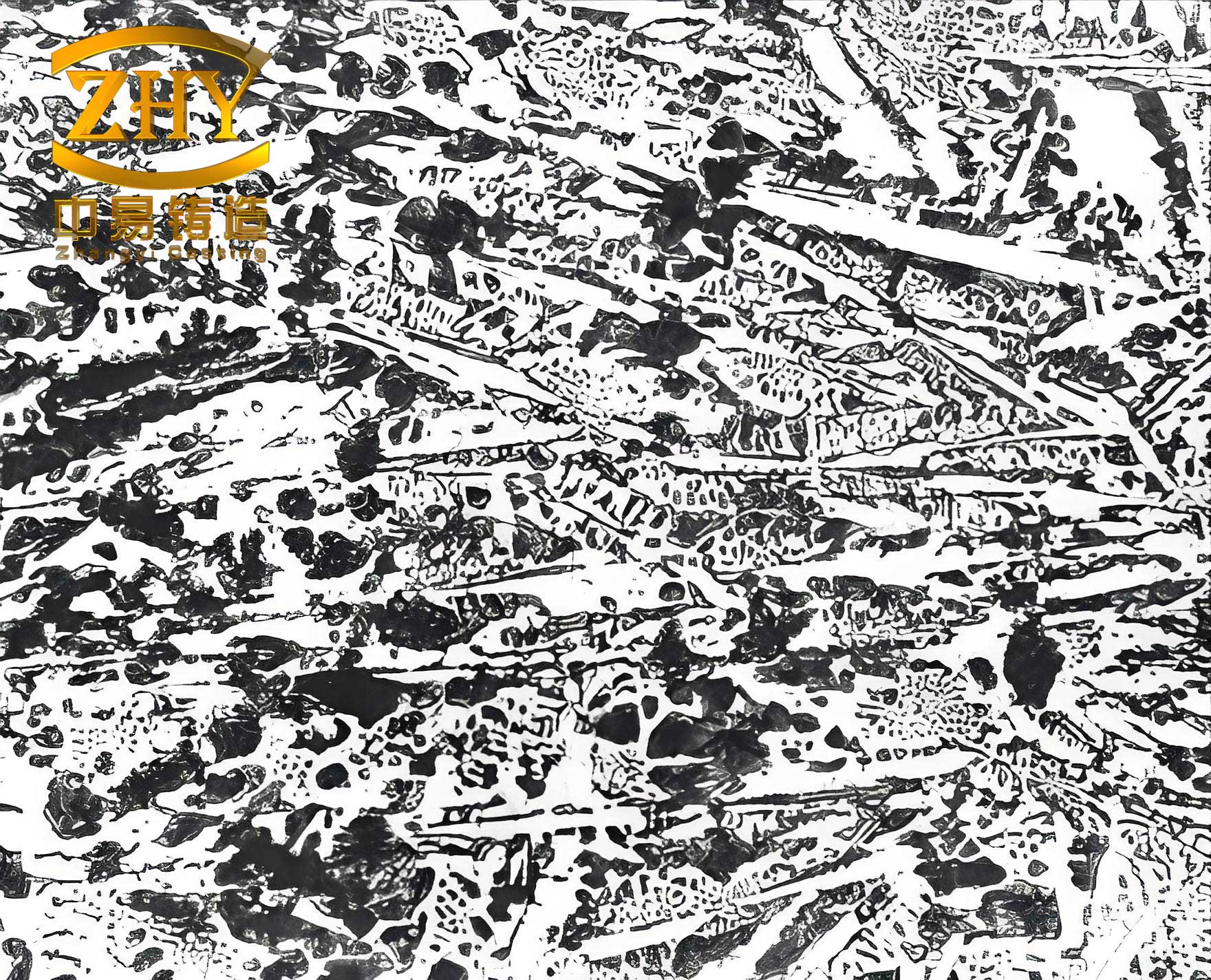
Fundamental Analysis: The Exceptional Weldability Challenges of White Cast Iron
Mill rolls, particularly those used in hot rolling stands, are frequently manufactured from indefinite chill or alloyed white cast iron. These are large castings, often weighing several tons. Failures are typically localized, manifesting as spalling, shelling, or cracking on the working surface. The microstructure of the working surface layer, which is the primary concern for repair, consists of a continuous network of primary cementite (Fe3C) with small amounts of pearlite. This structure confers high hardness (55-65 HRC) but virtually no ductility.
The key metallurgical properties that define the weldability of white cast iron are summarized below and contrasted with gray iron for perspective:
| Property | White Cast Iron (Surface Layer) | Typical Gray Iron | Implication for Welding |
|---|---|---|---|
| Microstructure | Continuous cementite network + pearlite | Graphite flakes in ferrite/pearlite matrix | Extreme brittleness, no crack blunting. |
| Hardness (HRC) | 55 – 65 | ~20 – 30 (as-cast) | High wear resistance but low toughness. |
| Tensile Ductility (Elongation) | ~0% | 1 – 3% | Cannot accommodate strain; zero plastic deformation before fracture. |
| Linear Contraction Coefficient, α | High (~2x Gray Iron) | Lower | Generates significantly higher thermal stresses during cooling. |
| Notched Impact Toughness | Extremely Low | Low | Highly sensitive to stress concentrators like cracks. |
The primary welding problem is thermal stress cracking. The localised heating from the welding arc, combined with the material’s high coefficient of contraction (αwhite ≈ 2αgray), generates tremendous tensile stresses upon cooling. Since the white cast iron matrix has zero ductility, it cannot yield or plastically deform to relieve these stresses. Consequently, the crack sensitivity is extreme, far surpassing that of gray or even ductile iron. This can be conceptually modeled by considering the stress (σ) developed in a constrained condition during cooling from the welding temperature:
$$ \sigma = E \cdot \alpha \cdot \Delta T $$
Where E is Young’s modulus, α is the coefficient of thermal expansion/contraction, and ΔT is the temperature drop. For white cast iron, both E and α are significant, leading to high stress for a given ΔT. When this stress exceeds the local fracture strength, cracking occurs instantly.
Furthermore, to restore service functionality, the weld deposit must replicate the original roll’s surface properties—high hardness and wear resistance. This necessitates the use of hardfacing-type alloys, resulting in a martensitic/carbide matrix with inherently poor crack resistance. This requirement precludes the use of more forgiving “heterogeneous” filler metals (like nickel-base or copper-base alloys) commonly used for repairing gray iron, thereby compounding the technical difficulty.
Core Principles and Rejection of Conventional Wisdom
The uniquely poor weldability of white cast iron renders traditional arc “cold welding” processes, effective for gray iron, wholly inadequate. The classic doctrine of “low current, shallow penetration, short bead length, and thorough peening” consistently led to failure in our early trials, resulting in cracking along the fusion line or complete weld metal剥离. Analysis revealed two critical shortcomings of the conventional approach when applied to white cast iron:
- Ineffective Stress Mitigation: Peening alone is insufficient to manage the severe thermal stresses generated in large-volume repairs on this non-yielding base material.
- Poor Fusion Integrity: The mandated low current and shallow penetration prevent adequate metallurgical bonding, creating a planar, weak interface that becomes a preferential crack path.
Therefore, the new process was designed to solve these two problems fundamentally. The following sections detail the specific, interconnected measures that form the core of this innovative repair strategy.
The Innovative Repair Process: A Synergistic Methodology
1. Rectangular Groove Geometry
The initial preparation of the damaged area is crucial. The common practice of creating a V-shaped or U-shaped groove (wider at the top) is detrimental. This geometry results in a greater volume of weld metal at the top, causing contraction stresses to increase disproportionately as welding progresses, often leading to surface cracking at the fusion line upon completion.
The recommended geometry is a rectangular-section groove with vertical sides and a flat bottom. This symmetrical profile ensures a more uniform distribution of weld metal and contraction stresses throughout the depth of the repair. Mechanically, this configuration embeds the weld like a vertical key into the base metal, offering superior resistance to crushing and fatigue loads during service. The inherent brittleness of the white cast iron layer makes this groove easy to prepare using grinding disks, chisels, and hammers.
2. High-Current Deposition with Strategic High-Temperature Peening
The first layer deposited is the critical fusion/transition zone. Our experiments demonstrated that the parameters for this layer are pivotal.
High-Current Advantage: Contrary to traditional practice, using a high welding current (approximately 1.5 to 2 times the normal value, or the maximum before the electrode overheats) is beneficial. Comparative tests showed distinct crack propagation differences:
- Low Current: Cracks propagated directly along the fusion line, indicating a weak, poorly fused interface.
- High Current: Cracks occurred in the base metal, far from the fusion zone, which itself remained intact.
Metallographic and microprobe analysis confirmed that high current induces deep penetration, achieving excellent fusion. This creates a wider, more diffuse fusion zone with a gradual compositional gradient, reducing the abrupt property mismatch and associated crack sensitivity. Furthermore, it promotes a convoluted, interlocking fusion boundary (see conceptual diagram below) rather than a straight plane. This tortuous path significantly increases the energy required for crack propagation, enhancing resistance to both cracking and剥离.
Strategic Peening Protocol: While high current increases heat input and thermal stress, it necessitates a smarter approach to stress relief than mere frequent peening. Unrestrained heavy peening can cause impact-fatigue damage at the fusion zone. The new protocol emphasizes:
- Peening Temperature: Peening is initiated at a high temperature (around 600-700°C), where the metal has sufficient plasticity to absorb the hammer impact and undergo beneficial compressive deformation. Peening is stopped below 300°C, where the metal becomes too hard and brittle, risking damage.
- Peening Force and Frequency: A heavy hammer (~1.5 kg) is used for high-impact peening, but the number of strikes is minimized (typically 2-3 per small segment). This provides effective stress relief through plastic deformation while minimizing repeated impact cycles on the fusion line. Residual stress measurements using X-ray diffraction confirmed that this method leaves a beneficial compressive stress state (-200 to -400 MPa) in the vicinity of the fusion zone.
The synergy of High-Current Deposition + High-Temperature Heavy Peening with Reduced Strikes produces a sound, well-fused foundation layer.
3. Segmented and Isolated Buildup Strategy
Repair volumes can be large (e.g., 200mm x 200mm x 50mm). A continuous, sequential buildup over such an area leads to severe stress accumulation and high restraint, inevitably causing cracking. The novel solution is the “Segmented and Isolated Buildup” method.
After depositing the first continuous layer across the entire groove bottom, the repair area is conceptually divided into several isolated blocks (e.g., 50mm x 50mm each). These blocks are separated from each other and from the surrounding base metal by deliberate gaps of 10-15mm.
Welding proceeds independently within each isolated block, using a skip-sequence to distribute heat. Crucially, the gaps are left unfilled. Each block is built up to its final height (including machining allowance) as an independent island. This allows each segment to expand and contract with considerable freedom, preventing the superimposition of stresses from adjacent welds. The entire weldment remains in a low-stress state throughout this phase.
Only after all blocks are built up are the inter-block and peripheral gaps filled. Filling these narrow gaps requires a relatively small amount of metal. Using a sharp chisel for high-temperature peening during this final step applies significant lateral compressive force, effectively managing the remaining stresses. This method decouples stress management from being solely reliant on peening, thereby protecting the critical root fusion zone from cumulative damage.
4. Final Formation of the Peripheral Fusion Zone
In conventional repair, the perimeter fusion zone is created first. This subjects it to the full thermal and mechanical cycling of all subsequent weld passes and peening operations, increasing the risk of thermal/mechanical fatigue failure.
The new process inverts this sequence. The peripheral fusion zone is formed last, during the final step of filling the gap between the pre-built central weld mass and the base metal. This means the critical fusion boundary undergoes only one major thermal cycle and minimal peening, drastically improving its reliability. For large-volume repairs, this advantage is particularly pronounced.
The perimeter gap is itself divided into short segments (e.g., 50-80mm), which are filled in a skip-sequence. A slightly higher current is used to ensure full penetration, with the arc angled towards the weld mass to avoid overheating the white cast iron base metal.
5. “Hard-Soft-Hard” Weld Metal Design
To enhance the service life of the repair under severe rolling impact (especially during bite), the weld deposit is designed with a layered structure:
- Base Layer (Fusion Zone): Specific electrode for bonding to white cast iron.
- Intermediate “Soft” Layer: A buffer layer of high-toughness, lower-hardness weld metal (e.g., a low-alloy steel type) is deposited. This layer absorbs impact energy and blunts crack propagation.
- Top “Hard” Working Layer: A final layer of high-hardness, abrasion-resistant alloy matching the original roll surface properties.
This “Hard-Soft-Hard” composite structure significantly improves the roll’s resistance to spalling, increasing the service tonnage between repairs by a factor of 2-3 compared to a monolithic hard overlay.
Process Summary and Comparative Analysis
The following table contrasts the key parameters and philosophy of the traditional gray iron cold weld process with the new white cast iron roll repair process:
| Aspect | Traditional Gray Iron “Cold” Repair | Innovative White Cast Iron Roll Repair |
|---|---|---|
| Groove Geometry | V-shaped or U-shaped | Rectangular with vertical sides |
| Welding Current | Low (minimal dilution) | High (for deep penetration & fusion) |
| Fusion Zone Goal | Minimal, planar interface | Maximized, tortuous interface |
| Peening Strategy | Frequent, at all temperatures | Heavy, limited strikes, at high temp only (>300°C) |
| Buildup Sequence | Continuous, layer-by-layer over whole area | Segmented, isolated blocks built independently |
| Peripheral Fusion Zone | Formed first | Formed last |
| Stress Management Focus | Primarily through peening | Primarily through geometric freedom (isolation), peening is secondary |
| Weld Metal Design | Often homogeneous (e.g., Ni-base) | Composite “Hard-Soft-Hard” layered structure |
Production Application and Results
This methodology has been successfully applied to repair over one hundred white cast iron work and backup rolls in hot strip and plate mills. The process is robust, relatively simple to execute with standard manual arc welding equipment, and does not require preheating, making it highly attractive for in-situ repair in mill environments. After brief training, plant personnel can consistently achieve repairs that meet the relevant roll reconditioning standards.
The economic impact is substantial. Considering the cost of a new work roll can exceed $50,000 (and backup rolls much more), the direct savings from avoiding scrap are significant. Post-repair performance data indicates that a repaired roll can, on average, produce an additional 10,000 to 15,000 tons of plate before requiring reconditioning. For a major steel producer, the annual economic benefit from implementing this repair strategy can easily reach several million dollars, factoring in both roll savings and sustained production revenue.
Extended Discussion: Theoretical Considerations on Stress and Microstructure
The success of the segmented isolation technique can be further understood through a simplified model of stress development. In a continuous weld, the final stress state is an accumulation from each pass. The total residual stress (σres) can be considered a summation:
$$ \sigma_{res} \approx \sum_{i=1}^{n} (\sigma_{thermal,i} – \sigma_{relief,i}) $$
where n is the number of passes, σthermal,i is the thermally induced stress from pass i, and σrelief,i is the stress relieved in pass i (via peening or yielding). In large, restrained welds on white cast iron, σrelief,i is very small due to lack of ductility, leading to σres growing dangerously with n.
In the isolated block method, each block j is essentially a small, less-restrained weld. Its final stress σres,j is lower. The final step of connecting the blocks involves welding thin gaps. The stress from this final operation (σfinal) is largely confined to the newly added metal and is effectively managed by high-temperature peening. The overall stress in the main body of the repair remains close to the lower σres,j values. This can be expressed as:
$$ \sigma_{total} \approx \max(\sigma_{res,1}, \sigma_{res,2}, …, \sigma_{res,k}, \sigma_{final}) $$
where k is the number of isolated blocks. This prevents the dangerous summation observed in continuous welding.
Furthermore, the importance of a diffuse fusion zone is critical. The hard, brittle white cast iron and the hard, strong weld metal form a bi-material interface. The risk of interfacial fracture is governed by factors including the stress intensity and the toughness of the interface region. By creating a broad, compositionally graded zone through high-current welding, we effectively increase the fracture toughness (KIc) of this critical region, making it more resistant to crack initiation than the base white cast iron itself. This explains why cracks, when they occur in test specimens, run into the base metal rather than along the fusion line.
Conclusion and Broader Implications
1. The repair of white cast iron mill rolls is uniquely challenging due to the material’s nil ductility and high thermal contraction. A successful process must solve the dual problems of managing severe thermal stresses and ensuring excellent metallurgical fusion.
2. The core innovation is the “Segmented and Isolated Buildup” strategy. This, combined with rectangular groove geometry, final formation of the peripheral fusion zone, and a composite “Hard-Soft-Hard” weld design, ensures the repair remains in a low-stress state throughout the operation.
3. For white cast iron, peening cannot be the sole stress-relief mechanism. A protocol of high-temperature, heavy-but-minimal peening must be precisely timed to be effective without causing impact damage.
4. High welding current is advantageous for achieving deep penetration and a tortuous, high-integrity fusion zone, which is more crack-resistant than the base white cast iron itself.
5. This holistic methodology has proven highly successful in industrial production, delivering excellent technical results and major economic benefits. The underlying principles of stress management through geometric control and interface engineering are also applicable and informative for repairing other large, brittle cast iron components such as heavy machinery beds or large gear blanks, where traditional welding approaches are similarly prone to failure.