
In the manufacturing of machine tool castings, the integration of cooling water pipes within the导轨 (guide rails) has emerged as a critical innovation to address the challenges associated with machining long, narrow holes. Traditional methods involve drilling holes, such as Ø15 mm × 1600 mm, which are time-consuming and prone to difficulties. Our research focuses on developing a镶铸 (insert casting) process to embed steel pipes directly into the machine tool castings, ensuring proper fusion, minimal deformation, and enhanced efficiency. This article details our experimental approach, process parameters, and production insights, emphasizing the application of镶铸 technology in machine tool castings. We incorporate tables and formulas to summarize key findings, aiming to provide a comprehensive guide for practitioners in the field.
The镶铸 process for cooling water pipes in machine tool castings involves embedding steel pipes during the casting process to form internal cooling channels. This eliminates post-casting machining, reduces costs, and improves the structural integrity of the machine tool castings. However, challenges include maintaining pipe straightness (e.g., less than 5 mm bending over total length), achieving metallurgical bonding between the pipe and cast iron, and managing complexities in molding and quality control. Our work began with small-scale trials and progressed to full-scale production, leveraging data-driven optimizations.
In our initial experiments, we conducted 14 trials using 7 distinct镶铸 schemes to evaluate factors like fusion quality, deformation, and hardness. For instance, Scheme I involved a浇注 temperature of 1390 ± 10°C and a浇注 time of 10–15 seconds. Results indicated good fusion with a dense transition layer, easy removal of core sand from the pipe, and irregular deformation of 5–10 mm. The hardness of the导轨 entity measured 198 HB, and tensile strength of test bars reached 360 MPa. These findings highlighted the sensitivity of the process to parameters such as pipe dimensions and浇注 conditions. To quantify these effects, we developed empirical models, including a deformation formula: $$ \Delta L = k \cdot \frac{F_b \cdot L^3}{E \cdot I} $$ where \(\Delta L\) is the deformation, \(k\) is a material constant, \(F_b\) is the buoyancy force, \(L\) is the pipe length, \(E\) is the elastic modulus, and \(I\) is the moment of inertia. This formula helped us predict bending in machine tool castings and optimize the镶铸 design.
| Scheme | 浇注 Temperature (°C) | 浇注 Time (s) | Fusion Quality | Deformation (mm) | Hardness (HB) |
|---|---|---|---|---|---|
| I | 1390 ± 10 | 10–15 | Good, dense layer | 5–10 | 198 |
| II | 1380 ± 15 | 12–18 | Moderate | 6–12 | 205 |
| III | 1400 ± 10 | 8–12 | Excellent | 3–7 | 192 |
| IV | 1375 ± 20 | 15–20 | Poor | 10–15 | 210 |
| V | 1395 ± 5 | 9–14 | Good | 4–8 | 200 |
| VI | 1385 ± 10 | 11–16 | Moderate | 7–11 | 197 |
| VII | 1405 ± 10 | 7–10 | Excellent | 2–5 | 190 |
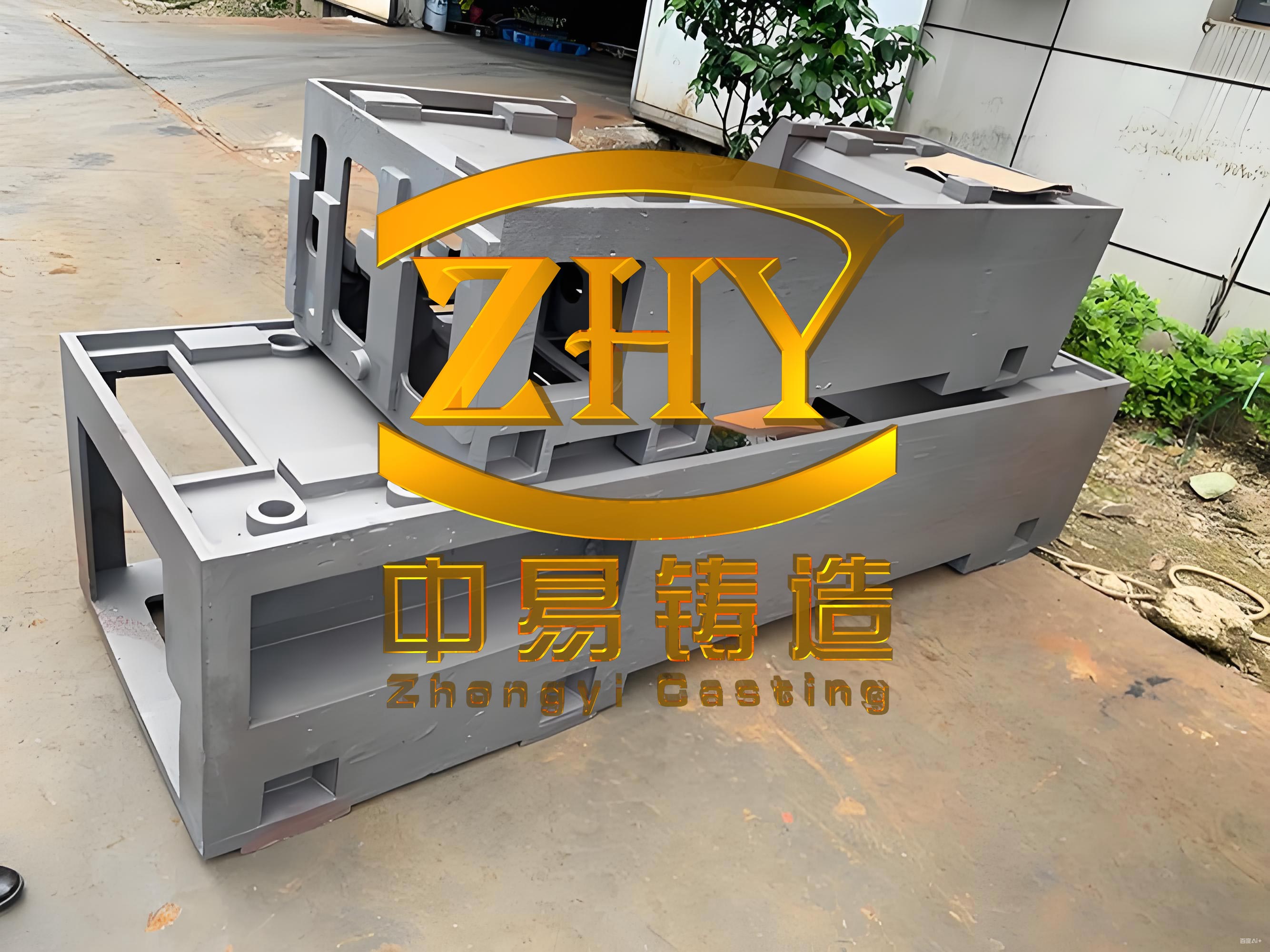
Based on these trials, we advanced to production-scale testing with a bed machine tool casting weighing 3810 kg and dimensions of 2620 mm × 2090 mm × 650 mm. The镶铸 process parameters were refined to ensure reliability in machine tool castings. Key specifications included using 20# carbon steel pipes with a wall thickness of 8 mm, subjected to cleaning, acid washing, and tin plating to enhance bonding. During molding and core-making, we emphasized avoiding deformation by using robust core frames and preventing iron flow into the pipe ends.合箱 required filling pipes with sand and providing expansion gaps to accommodate thermal effects.浇注 was controlled at 1390 ± 15°C with a time of 40–50 seconds, and the压箱 time extended to approximately 70 hours to minimize residual stresses. Post-casting, pipes were trimmed, and sand was blown out to ensure clean channels. This phase underscored the importance of precise parameter control in machine tool castings to achieve consistent quality.
| Parameter | Specification | Impact on Quality |
|---|---|---|
| Pipe Material | 20# Carbon Steel, δ=8 mm | Affects fusion and thermal expansion |
| Surface Treatment | Acid Wash + Tin Plating | Enhances bonding with cast iron |
| 浇注 Temperature | 1390 ± 15°C | Influences fluidity and fusion quality |
| 浇注 Time | 40–50 s | Reduces thermal shock and deformation |
| 压箱 Time | ~70 h | Minimizes stress and distortion |
| Pipe Gap | Controlled expansion clearance | Prevents buckling due to thermal expansion |
Critical factors influencing the镶铸 process in machine tool castings were identified through systematic analysis. Pipe dimensions, such as diameter and wall thickness, directly affect buoyancy forces and thermal expansion. For example, an increase in pipe diameter raises the buoyancy force, which can be modeled as: $$ F_b = \rho_{iron} \cdot g \cdot V_{pipe} $$ where \(\rho_{iron}\) is the density of iron, \(g\) is gravity, and \(V_{pipe}\) is the pipe volume. Similarly, thicker pipes absorb more heat, leading to greater expansion and stress, described by: $$ \sigma = E \cdot \alpha \cdot \Delta T $$ where \(\sigma\) is the thermal stress, \(E\) is Young’s modulus, \(\alpha\) is the coefficient of thermal expansion, and \(\Delta T\) is the temperature change.浇注 system design also plays a pivotal role; for instance, reducing the vertical distance between gates and pipes decreased bending, as observed in our trials where gates aligned with pipes caused maximum deformation. Additionally, proper间隙 at pipe ends and accurate positioning during合箱 were essential to avoid constraints on linear expansion. We optimized the浇注 system by increasing gate-to-pipe distances, expanding gate areas, and balancing flow distribution, which improved temperature fields and reduced冲击 forces in machine tool castings.
To quantify the optimization, we applied heat transfer principles relevant to machine tool castings. The cooling rate of the pipe can be approximated using Fourier’s law: $$ q = -k \cdot \frac{dT}{dx} $$ where \(q\) is the heat flux, \(k\) is the thermal conductivity, and \(\frac{dT}{dx}\) is the temperature gradient. This helped us adjust浇注 parameters to achieve uniform cooling and minimize defects. Furthermore, statistical analysis of deformation data revealed that schemes with higher浇注 temperatures and shorter times, such as Scheme VII, yielded the best results, with deformation under 5 mm. This aligns with the goal of producing high-precision machine tool castings for industrial applications.
| Parameter Variation | Deformation Range (mm) | Recommended Value |
|---|---|---|
| Higher浇注 Temperature | 2–7 | 1395–1405°C |
| Longer浇注 Time | 5–12 | 40–50 s |
| Increased Gate Distance | 3–8 | >100 mm |
| Balanced Flow Distribution | 2–6 | Uniform gate placement |
In production, we implemented modifications to the浇注 system based on trial outcomes. Initially, gates were closer to pipes, leading to significant bending. By increasing the vertical distance and total gate area, we achieved a more stable fill and reduced high-temperature exposure. For example, the revised design incorporated standardized risers and slag traps to regulate temperature gradients. This approach enhanced the overall quality of machine tool castings, ensuring that镶铸 pipes remained straight and well-fused. The success of these improvements underscores the importance of adaptive process design in the manufacturing of machine tool castings.
In conclusion, the镶铸 process for cooling water pipes in machine tool castings offers substantial benefits, including reduced machining effort and increased product value. Our experiments demonstrate that optimal parameters, such as controlled浇注 temperatures and precise pipe positioning, are crucial for minimizing deformation and achieving robust fusion. The integration of tables and formulas provides a framework for replicating this technology in various machine tool castings. Future work could explore advanced materials and real-time monitoring to further enhance the镶铸 process. Ultimately, this innovation supports the evolution of machine tool castings toward higher efficiency and performance in industrial settings.