
Abstract
Crane drums, especially those in casting cranes, play a crucial role in ensuring the safe and efficient operation of heavy-lifting equipment. The drum coupling, which connects the drum and the reducer, is a vital component influencing the overall performance of the crane. The installation accuracy of the drum coupling significantly impacts the crane’s lifespan, efficiency, and safety. This article delves into the various methods used to detect the installation accuracy of crane drum couplings, focusing on casting cranes. It summarizes three primary detection techniques and their advantages and limitations.
1. Introduction
Casting cranes, specifically designed for lifting molten metal, require exceptional safety standards due to their demanding working conditions. The drum coupling, responsible for transmitting torque between the drum and the reducer, is a critical component in the lifting mechanism. Ensuring the accurate installation of the drum coupling is vital for maintaining the crane’s performance and longevity.
This article aims to provide a comprehensive overview of the installation accuracy detection methods for crane drum couplings, emphasizing casting cranes. The discussion covers three primary detection techniques: the dial indicator method, the reference extension method, and the instrumentation method.
2. Drum Coupling Types and Functions
2.1 Types of Drum Couplings
Casting cranes typically employ two primary types of drum couplings: the specialized drum-type roller coupling and the spherical hinge drum coupling.
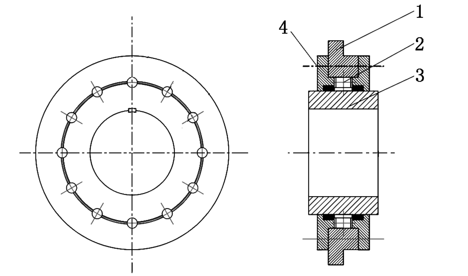
- Specialized Drum-Type Roller Coupling: This coupling comprises a hub, drum-type rollers, and a spoke. The hub connects to the reducer’s output shaft, while the spoke connects to the drum through an intermediate flange. The drum-type rollers, evenly distributed in a circular groove between the hub and spoke, transmit torque and support radial loads.
- Spherical Hinge Drum Coupling: This coupling consists of an outer spherical hinge sleeve and an inner spherical hinge head. The drum connects to the outer hinge sleeve, while the inner hinge head attaches to the reducer’s output shaft. It allows for significant axial misalignment and can withstand large loads.
2.2 Functions of Drum Couplings
Drum couplings play a pivotal role in the smooth and reliable operation of crane lifting mechanisms. Their primary functions include:
- Torque Transmission: Efficiently transmitting torque from the reducer to the drum, enabling the drum’s rotation.
- Radial Load Support: Bearing the radial loads generated during lifting operations.
- Misalignment Compensation: Accommodating minor misalignments between the reducer and drum axes.
3. Importance of Installation Accuracy
The installation accuracy of drum couplings significantly influences the crane’s overall performance, safety, and lifespan. Misalignments or improper installations can lead to:
- Vibration and Noise: Causing premature wear and tear on components.
- Decreased Efficiency: Reducing the crane’s lifting capacity and speed.
- Safety Hazards: Increasing the risk of component failures and accidents.
4. Installation Accuracy Detection Methods
To ensure the optimal performance and longevity of casting cranes, it is crucial to detect and correct any installation inaccuracies in drum couplings. The following sections detail three primary detection methods.
4.1 Dial Indicator Method
The dial indicator method, also known as the百分表法 (bai fen biao fa) in Chinese, is a precise technique for measuring axis tilt angles.
4.1.1 Procedure
- Setup: Attach a dial indicator with a magnetic base to the reducer’s output shaft. Position the dial indicator’s contact point against the edge of the drum flange.
- Rotation: Rotate the reducer’s output shaft slowly, causing the drum flange to rotate. Record the maximum and minimum dial indicator readings.
- Calculation: Measure the diameter (D_B) of the contact point on the drum flange. Calculate the tilt angle (β) using the formula:tanβ=DBLBwhere LB is the difference between the maximum and minimum dial indicator readings.
4.1.2 Advantages
- High Accuracy: Capable of achieving measurement accuracies up to 0.01 mm.
- Direct Measurement: Provides direct readings of tilt angles.
4.1.3 Limitations
- Time-consuming: Requires rotating the entire drum for a full cycle, increasing the measurement time.
- Labor-intensive: High operator involvement during the measurement process.
- Space Limitations: May not be feasible in cramped installations due to the dial indicator’s size and setup requirements.
4.2 Reference Extension Method
The reference extension method, a more practical approach during the installation process, uses basic tools to estimate axis tilt angles.
4.2.1 Procedure
- Setup: Secure a steel ruler or straightedge against a reference surface (e.g., the reducer housing).
- Measurements: Take measurements from the steel ruler to various points on the drum flange (e.g., top, bottom, left, right). Calculate the deviations from the ideal position.
- Calculation: Use the deviations and the distances between measurement points to calculate the tilt angles using trigonometric functions.
4.2.2 Advantages
- Simplicity: Requires minimal equipment and setup time.
- Efficiency: Faster than the dial indicator method, ideal for installation process adjustments.
4.2.3 Limitations
- Indirect Measurement: Provides only an estimate of tilt angles.
- Error Prone: Susceptible to human error and environmental factors (e.g., uneven surfaces).
4.3 Instrumentation Method
The instrumentation method utilizes advanced surveying instruments, such as theodolites and levels, to indirectly measure axis tilt angles.
4.3.1 Procedure
- Leveling: Use a level to ensure the crane structure is horizontally aligned.
- Theodolite Measurements: Employ a theodolite to measure vertical and horizontal distances between specific points on the drum and reducer housing.
- Calculations: Based on the measured distances, calculate the tilt angles using trigonometric formulas.
4.3.2 Advantages
- Versatility: Suitable for large-scale installations and complex geometries.
- Accuracy: Can achieve high measurement accuracies with skilled operators.
4.3.3 Limitations
- Specialized Skills: Requires trained personnel to operate the instrumentation accurately.
- Cost: More expensive than basic measurement tools.
- Time-consuming: Involves multiple measurements and calculations.
5. Comparison of Detection Methods
The following table summarizes the key characteristics of the three installation accuracy detection methods:
| Detection Method | Advantages | Limitations |
|---|---|---|
| Dial Indicator Method | High accuracy (0.01 mm) | Time-consuming, labor-intensive, space limitations |
| Reference Extension Method | Simplicity, efficiency during installation | Indirect measurement, prone to human error |
| Instrumentation Method | Versatility, high accuracy with skilled operators | Specialized skills required, expensive, time-consuming |
6. Conclusion
Ensuring the installation accuracy of crane drum couplings is crucial for maintaining the performance, safety, and longevity of casting cranes. The three primary detection methods—dial indicator, reference extension, and instrumentation—each have their unique advantages and limitations. Selection of the appropriate method depends on the specific installation requirements, available resources, and operator skills. By employing these techniques, crane technicians can effectively detect and correct installation inaccuracies, ultimately enhancing the overall reliability and efficiency of casting cranes.