
In my research, I focused on the forming technology of an integral pump valve with a complex internal structure. Pump valves and similar fluid-control castings occupy an important position in the casting industry because they are used in many industrial fields, they are required in large quantities, and they often must satisfy strict requirements for pressure tightness, dimensional accuracy, surface quality, and internal soundness. Among these products, complex pump valve bodies are especially important because they represent a strong trend in product development and because they create significant challenges for conventional foundry processes. In my work, I treated the integral pump valve not as a simple collection of separately cast or separately assembled parts, but as a single complex casting that must be produced with a coherent mold design, a reliable core, a controlled filling process, and a validated post-processing route.
Traditional sand mold casting remains the most widely used production method for pump valve castings. In sand mold casting, a cavity is formed in compacted or bonded sand, a core is placed to create internal passages, and liquid metal is poured into the cavity through a gating system. The method is flexible, economical, and suitable for many batch sizes. However, when the casting contains multiple curved internal channels, thin walls, intersecting passages, and asymmetrical mass distribution, the limitations of conventional sand mold casting become obvious. Hand-made cores, segmented cores, and adhesive bonding of core pieces can introduce dimensional errors, weak joints, gas defects, sand inclusions, and unstable filling behavior. For an integral pump valve, these problems can directly affect the service performance of the final product.
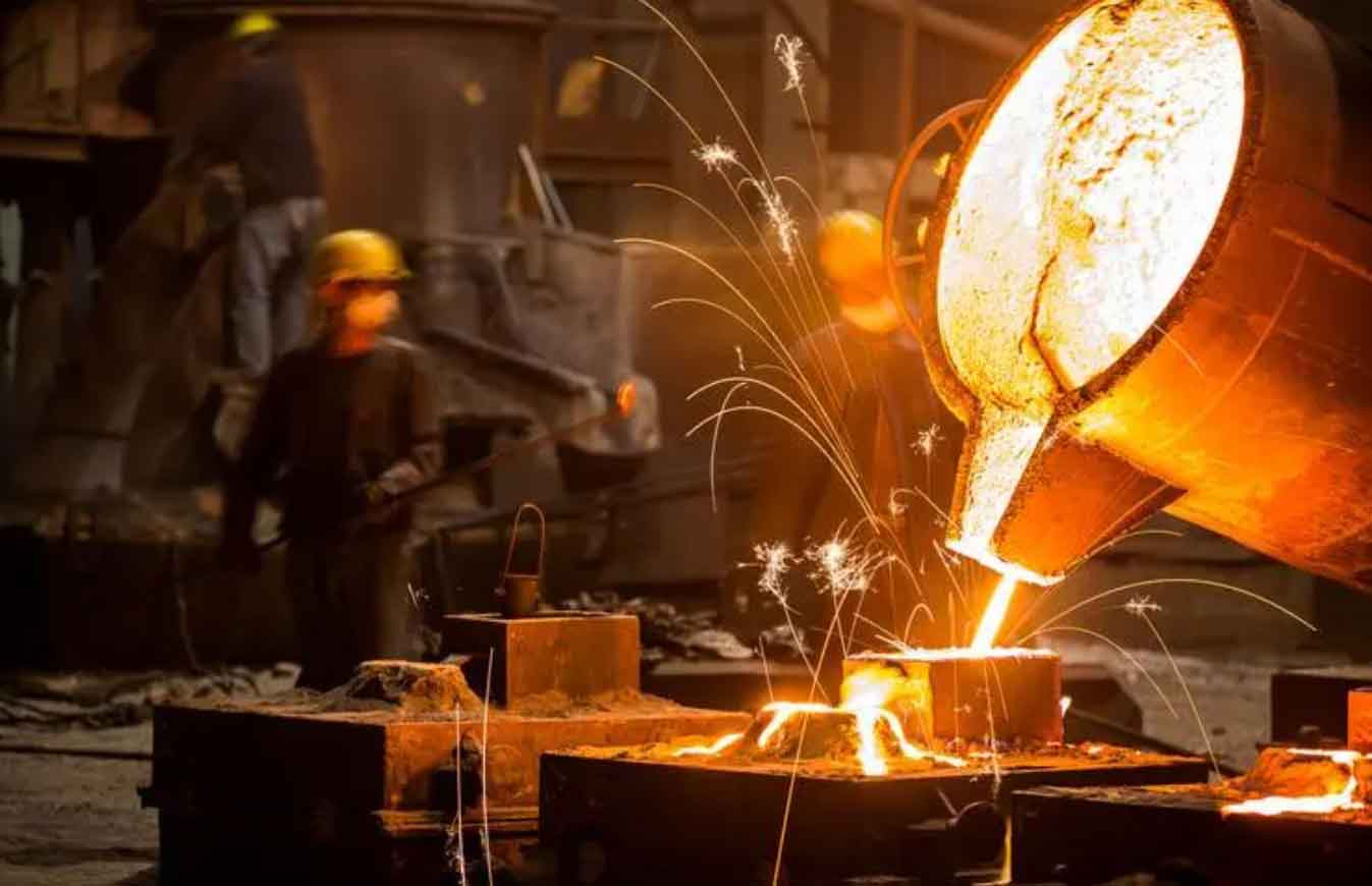
My central idea was to combine digital manufacturing, rapid prototyping, numerical simulation, and a controlled bottom-filling strategy in order to improve the quality of a complex integral pump valve. I selected a multi-way valve as the representative sample because its internal structure includes several narrow passages, junctions, and curved flow channels. This geometry is difficult to produce with conventional core assembly. By using an integral sand core produced through a rapid prototyping method, I avoided many of the errors caused by manual core segmentation and adhesive bonding. I then designed a casting plan, checked it with computer simulation, produced the mold and core, poured the part, and evaluated the result through three-dimensional scanning and sectioning. In parallel, I investigated a new casting concept called subsurface flow casting through water simulation experiments, because this method has the potential to make the filling of complex pump valve castings more stable and more controllable.
Why complex integral pump valves are difficult in sand mold casting. The difficulty comes from several sources. First, the internal channels often have small cross sections and long paths, so the core must have enough strength to resist erosion and buoyancy during pouring. Second, the wall thickness changes repeatedly, so the thermal field is non-uniform. Third, the gating system must fill the cavity without introducing turbulence, gas entrainment, or sand scouring. Fourth, the core cannot be easily repaired after assembly. Fifth, the dimensional tolerance of the internal passages is often as important as the external dimensions. In traditional sand mold casting, these issues are usually managed by experience, trial pours, and repeated adjustments. In my work, I tried to replace part of that trial-and-error approach with digital design, rapid manufacturing, and simulation.
Overview of special casting methods. Before selecting a process route, I reviewed the common alternatives to conventional sand mold casting. Investment casting can produce excellent surface finish and fine detail, but it is expensive for large pump valve bodies and requires a long process chain. Die casting is fast and precise, but the dies are costly and the process is usually limited to non-ferrous alloys and specific geometries. Pressure casting and squeeze casting can improve filling and density, but they require specialized equipment and are not always suitable for large complex ferrous valve bodies. Lost foam casting can reduce core assembly, but the pattern decomposition can produce gas-related defects. Each method has advantages, yet none is universally ideal for a complex integral pump valve. This motivated my hybrid approach: use sand mold casting as the base process, but upgrade it with rapid prototyping for the core, digital simulation for the gating design, and water simulation for the filling strategy.
Digital casting route. I organized my work along a digital casting route. The route began with a three-dimensional CAD model of the pump valve and its intended internal passages. From that model, I generated the casting model, the gating system, and the sand core. I then used computer simulation to check filling and solidification. After the design was accepted, I manufactured the external sand mold by computer numerical control engraving and manufactured the complex sand core by a rapid prototyping process. The core was coated, baked, assembled, and poured. Finally, the casting was cleaned, scanned, sectioned, and inspected. This route is summarized in the table below.
| Stage | Main input | Main output | Purpose |
|---|---|---|---|
| CAD design | Valve geometry, machining allowance, shrinkage | Casting model and core model | Define the target shape and internal passages |
| Rapid prototyping | Core CAD data | Integral sand core | Avoid manual core segmentation and bonding |
| Simulation | Casting model, material properties, gating system | Filling and solidification results | Evaluate the casting plan before pouring |
| Mold manufacturing | Mold CAD data | Top, middle, and bottom sand mold parts | Produce the external cavity and gating system |
| Pouring | Assembled mold, core, liquid metal | Cast pump valve blank | Obtain the integral casting |
| Post-processing | Cast blank | Cleaned and inspected part | Remove gating, check dimensions, verify internal quality |
Rapid prototyping methods. Rapid prototyping is based on the principle of discrete deposition or discrete consolidation. A three-dimensional CAD model is sliced into layers, and the part is built layer by layer. In my study, I considered several common rapid prototyping technologies. Stereolithography uses a liquid photopolymer and a laser to cure thin layers. Selective laser sintering uses powder and a laser to sinter selected regions. Fused deposition modeling extrudes a molten polymer filament through a nozzle. Laminated object manufacturing bonds and cuts sheet material. Each method has different accuracy, speed, material range, and cost. For a complex sand core used in sand mold casting, the selected method must produce a core with sufficient strength, acceptable surface quality, and reasonable processing time. I compared the main options in the table below.
| Method | Material form | Advantages | Limitations | Typical use |
|---|---|---|---|---|
| Stereolithography | Liquid resin | High accuracy, smooth surface, complex shapes | High cost, post-processing, resin shrinkage | Fine prototypes and patterns |
| Selective laser sintering | Powder | Wide material range, no support in many cases | Rough surface, powder removal, thermal distortion | Functional prototypes and sand cores |
| Fused deposition modeling | Filament | Simple, low equipment cost, easy material change | Visible layer lines, limited strength, slow for large parts | Plastic prototypes and fixtures |
| Laminated object manufacturing | Sheet material | Fast for large parts, low material cost | Limited geometry, delamination risk, waste removal | Large solid models |
| Profile failure rapid prototyping | Coated sand | Large format, high efficiency, good core strength after curing | Requires careful waste removal and post-curing | Integral sand cores for sand mold casting |
Profile failure rapid prototyping for the integral core. The method I used for the complex core is a profile failure rapid prototyping technique. It uses coated sand as the building material. The coated sand can be cured at a relatively low temperature, but it loses its bonding strength when overheated. In the building process, a heated plate consolidates the coated sand layer by layer. A laser then scans the contour of the part on each layer. The scanned region becomes over-cured and loses its effective bonding. After many layers are stacked, the failed contour lines form a continuous boundary around the desired part. The un-failed interior remains as the core, and the surrounding material can be removed after post-processing. This technique combines the speed of laminated manufacturing with the material advantages of coated sand. It is especially suitable for large sand cores because it does not require a pattern, a core box, or a long manual assembly process.
Subsurface flow casting concept. Subsurface flow casting is a controlled filling method. Instead of pouring from a fixed ladle or a fixed sprue, the pouring tube is kept below the metal surface during the entire filling process. The tube rises according to the rising metal level. The nozzle remains submerged, so the incoming metal does not fall freely through air and does not create a large open-channel impact zone. The filling front is therefore more stable. In my view, this method is attractive for complex pump valve castings because it can reduce turbulence, limit gas entrainment, and promote a favorable thermal gradient. The lower part of the casting solidifies first, while the upper part remains hotter and can feed the lower region. This is helpful for sequential solidification and for reducing shrinkage defects. I treated subsurface flow casting as a candidate technology for complex integral pump valves and used water simulation to examine its feasibility.
Governing equations for the subsurface flow process. I used Bernoulli-type relations and continuity to estimate the nozzle velocity and the required rising speed. For a control volume between the ladle and the mold, the energy equation can be written as
$$ \frac{P_1}{\rho g}+\frac{v_1^2}{2g}+H_1 = \frac{P_2}{\rho g}+\frac{v_2^2}{2g}+H_2+h_w $$
where \(P_1\) and \(P_2\) are pressures, \(v_1\) and \(v_2\) are velocities, \(H_1\) and \(H_2\) are liquid levels, \(\rho\) is density, \(g\) is gravitational acceleration, and \(h_w\) is the energy loss. For free outflow before the metal fully submerges the nozzle, the mold-side liquid level is small and the ladle velocity is small. The nozzle velocity can be approximated as
$$ v_2=\mu_1\sqrt{2gH_1} $$
where \(\mu_1\) is the free-outflow discharge coefficient. For submerged outflow, the driving head becomes the difference between the ladle level and the mold level. The equation becomes
$$ v_2=\mu_1\sqrt{2g(H_1-H_2)} $$
The discharge coefficient depends on the nozzle geometry, surface roughness, and internal losses. I also used the continuity relation
$$ Q_1=Q_2=Q_3,\qquad v_1A_1=v_2A_2=v_3A_3 $$
where \(Q\) is volumetric flow rate and \(A\) is cross-sectional area. For a mold containing a core, the local rising speed of the liquid surface is related to the instantaneous mold free area:
$$ v_{\text{riser}}=\frac{Q_{\text{nozzle}}}{A_{\text{mold}}(z)-A_{\text{core}}(z)} $$
This relation was the basis for my control curve. At each height \(z\), I estimated the free cross-sectional area and converted the measured nozzle flow rate into a required vertical speed for the pouring tube. In this way, the tube could follow the liquid surface instead of moving at a constant speed.
Water simulation platform. Because the actual subsurface flow process occurs inside an opaque sand mold, I could not directly observe the metal flow. I therefore built a water simulation platform. Water is a convenient analogue for liquid metal in filling studies because the Reynolds number, Froude number, and other dynamic similarity parameters can be scaled. I used transparent acrylic boxes to represent the mold cavity, and I used water as the working fluid. The pouring tube was mounted on an industrial robot arm. The robot controlled the vertical motion of the tube and the opening of a solenoid valve. This arrangement allowed me to reproduce the rising speed curve and observe the flow field directly. The robot had fast response and high positioning accuracy, which was important for variable cross-section filling. The water simulation platform included a ladle, a tundish, a mold cavity, a slag trap, and the moving pouring tube. I used this platform to measure flow coefficients, study slag removal, compare nozzle outlets, optimize the tube path, and test the multi-way valve core.
Measurement of discharge coefficients. The discharge coefficient of a pouring tube is not a universal constant. It depends on the tube diameter, outlet shape, internal length, and surface conditions. I measured the flow rate of several tube designs by filling a known volume and recording the filling time. At first, my calculated tube speeds did not match the observed water level rise. The tube moved too slowly and became progressively deeper below the surface. I found that the measured filling time included the time required for water to travel from the top of the tube to the nozzle. This travel time was about 0.8 s and was nearly independent of tube diameter and outlet type. After subtracting this delay, the corrected flow rates and velocities became consistent with the observed surface rise. The comparison is shown below.
| Tube outlet | Initial filling time (s) | Corrected filling time (s) | Nozzle velocity (mm/s) | Barrel surface rise (mm/s) | Mold surface rise (mm/s) |
|---|---|---|---|---|---|
| Straight, 20 mm | 2.8 | 1.5 | 1332.5 | 53.3 | 7.0 |
| Straight, 16 mm | 2.0 | 1.9 | 1644.5 | 42.1 | 5.5 |
| Straight, 12 mm | 2.8 | 2.3 | 2415.5 | 34.8 | 4.6 |
| Side, 8.5 mm | 3.9 | 3.0 | 1847.8 | 26.7 | 3.5 |
| Side, 11 mm | 2.6 | 2.4 | 1376.0 | 33.3 | 4.4 |
| Side, 14 mm | 2.3 | 2.0 | 1020.4 | 40.0 | 5.2 |
After correcting the travel time, I entered the new speeds into the robot program. The tube then followed the water surface much more accurately. The tube remained submerged at a stable depth, and the filling process became smoother. This was an important practical result because it showed that even a simple water simulation can reveal timing errors that would be difficult to detect in a real sand mold casting trial.
Role of the tundish. I inserted a tundish between the ladle and the mold. The tundish had an inlet chamber, an outlet chamber, and a baffle with a bottom gap. The purpose was to reduce the kinetic energy of the incoming stream, allow slag and low-density inclusions to float, and prevent the first turbulent portion of the stream from entering the mold. I tested two operating modes. In the first mode, the tundish was filled and then the valve was opened without replenishment. In the second mode, the tundish was kept full during the entire pour. In the first mode, the baffle held back floating impurities while the water level was above the baffle. However, near the end of discharge, the level dropped below the baffle and the remaining impurities could pass into the mold. The outlet stream also entrained gas. In the second mode, the tundish remained full, so the baffle continued to block floating impurities, and the outlet stream stayed stable. I concluded that continuous replenishment of the tundish is preferable for sand mold casting of quality pump valve parts.
| Tundish mode | Slag retention | Gas entrainment | Flow stability | Recommendation |
|---|---|---|---|---|
| Fill and discharge without replenishment | Good at first, poor near the end | Strong near the end | Decreases with time | Not preferred |
| Continuous replenishment | Good throughout | Low | Stable throughout | Preferred |
Role of the slag trap. I also placed a slag trap at the bottom of the mold. The first liquid that leaves the pouring tube is usually the most turbulent and may contain gas bubbles, loose sand particles, and oxide inclusions. If this first liquid enters the main cavity directly, it can create porosity, sand holes, or inclusions. The slag trap captures this unstable first portion. In my water simulation, the first stream produced many bubbles and irregular flow patterns. Once the water level covered the nozzle, the flow became much steadier, and the gas bubbles gradually disappeared. When the nozzle was lifted out of the slag trap and into the mold, the liquid entering the cavity was clean and stable. The slag trap therefore acted as a buffer between the initial transient flow and the main cavity. For a complex integral pump valve, this is valuable because internal passages are difficult to inspect and repair after sand mold casting.
Effect of outlet type and outlet area. I compared straight outlets and side outlets. Straight outlets discharge downward, creating a turbulent zone below the nozzle. Side outlets discharge laterally, creating a turbulent zone on the sides of the tube. I used three straight tubes with diameters of 12, 16, and 20 mm and three side-outlet tubes with outlet diameters of 8.5, 11, and 14 mm. The observations are summarized below.
| Outlet type | Approximate outlet area | Observed turbulence | Effect on slag trap | Suitable condition |
|---|---|---|---|---|
| Straight, large diameter | Large | Shallow but wide zone below nozzle | Can disturb settled impurities | Simple lower geometry |
| Straight, small diameter | Small | Localized and weak overall disturbance | Moderate | Narrow riser-like regions |
| Side, large outlet | Large | Lateral zone close to nozzle | Less disturbance at bottom | Wide mold sections |
| Side, small outlet | Small | Very limited lateral disturbance | Low | Complex internal cores |
In general, a smaller outlet area produced a more localized flow disturbance. A larger outlet area produced a wider but shallower disturbance. Side outlets were more favorable when the slag trap contained loose impurities, because the downward flow of a straight outlet could re-entrain particles that had already settled. For the multi-way valve, I preferred a side outlet with a moderate area because it reduced direct impingement on the bottom of the mold and kept the most turbulent region away from the complex core passages.
Path design and optimization. The path of the pouring tube is a controlled trajectory. It starts below the slag trap, rises with the liquid surface, passes through the slag trap opening, enters the mold cavity, and then follows the local free area until the end of filling. I found two problems in the initial path. First, if the nozzle left the slag trap too early, the turbulent zone could still act on the slag trap and lift impurities into the mold. Second, if the tube passed through the narrow slag trap opening too slowly, the liquid surface could rise above the opening and cause splashing. I solved these problems by using a side outlet, starting at the bottom of the slag trap, waiting until the nozzle was fully submerged, and then moving quickly through the narrow transition. After the nozzle reached the lower part of the mold cavity, it waited again until the surface covered the outlet, and then it followed the calculated speed curve. This optimized path reduced splashing and kept the slag trap quiescent after the tube left it.
Variable cross-section filling. Real pump valve molds do not have a constant cross section. The presence of the core changes the free area at every height. I tested two core models in water simulation: one with a gradual change in cross section and one with a sudden change. For a sudden change, the robot can switch speed almost instantaneously. For a gradual change, I divided the height into small intervals and used an average area for each interval. The accuracy increases as the number of intervals increases. I represented the local area by
$$ A_{\text{free}}(z)=A_{\text{mold}}(z)-A_{\text{core}}(z) $$
and I computed the local tube speed as
$$ v_{\text{tube}}(z)=\frac{Q_{\text{nozzle}}}{A_{\text{free}}(z)} $$
The water simulation showed that the robot could follow both gradual and sudden area changes. The pouring tube remained below the water surface, and the flow field stayed stable. This confirmed that the control strategy was suitable for the actual multi-way valve, whose internal core creates many changes in free area.
Water simulation with the multi-way valve core. I placed the actual multi-way valve core inside the water simulation mold. This was the most direct test of the subsurface flow concept for the target part. I divided the core into fourteen height segments and calculated the free area of each segment. To obtain the core cross-sectional area, I used a Boolean intersection between a thin plane and the core model. I compared plane thicknesses of 0.1 mm, 0.3 mm, and 1.0 mm. The 0.1 mm and 0.3 mm planes gave similar areas, while the 1.0 mm plane gave a noticeably larger area and produced a speed curve that did not match the observed surface rise. I therefore used a 0.3 mm plane for area extraction. The selected sections and the calculated tube speeds are listed below.
| Segment | Core height (mm) | Calculated rising speed (mm/s) |
|---|---|---|
| 1-1 | 10 | 8.9 |
| 1-2 | 15 | 8.3 |
| 1-3 | 20 | 7.2 |
| 2 | 25 | 6.6 |
| 3 | 41 | 5.4 |
| 4 | 51 | 5.7 |
| 5 | 63 | 5.3 |
| 6 | 68 | 5.3 |
| 7 | 83 | 6.0 |
| 8 | 87 | 5.2 |
| 9 | 92 | 4.8 |
| 10 | 97 | 5.1 |
| 11 | 115.5 | 4.8 |
| 12 | 130.5 | 5.3 |
When these speeds were entered into the robot controller, the pouring tube followed the water surface throughout the filling process. The tube remained submerged, and the flow did not create excessive splashing or entrainment. This result supported the feasibility of subsurface flow casting for the integral multi-way valve. It did not replace the final metal trial, but it provided confidence that the motion control and the filling strategy were practical.
Casting plan for the multi-way valve. I designed the casting plan for the multi-way valve with several goals in mind: stable filling, minimal core erosion, easy core location, complete filling of narrow passages, and a favorable solidification sequence. I placed the large flat face of the core upward to reduce direct metal impingement on the most delicate internal passages. I selected an elevated pouring position so that the bottom-filling gating system could feed the cavity from below. I considered the material and shrinkage behavior. For the numerical simulation, I used a gray iron grade to represent the thermal properties. For the actual trial pour, I used HT250 gray iron because it was available and suitable for the valve body. The linear shrinkage was taken as 0.9% for the pattern design. Machining allowance was added to the surfaces that required subsequent machining.
Gating system design. I used a bottom-fill, open gating system. The choke was placed at the ingate. The area ratio of sprue to runner to ingate was set to 1.5:2:1, which made the ingate the smallest cross section and therefore the flow-control point. I estimated the pouring time with the empirical relation
$$ t=S\sqrt{W} $$
where \(W\) is the total metal weight and \(S\) is a coefficient related to the casting wall thickness. I used a choke area relation of the form
$$ A_{\text{choke}}=\frac{W}{\rho \mu t \sqrt{2gH_p}} $$
where \(\rho\) is the liquid density, \(\mu\) is the discharge coefficient, and \(H_p\) is the average static head. The design values I used were a pouring time of about 7.6 s, an ingate area of about 8.6 cm², a runner area of about 17.2 cm², and a sprue area of about 12.9 cm². The runner was arranged to reduce slag entry, and a slag trap was placed at the bottom. I did not add a conventional top riser. Instead, I relied on the graphitic expansion of cast iron and on the thermal gradient to reduce shrinkage defects. This choice was also compatible with the bottom-fill strategy, because I wanted the lower part of the casting to solidify first while the upper part remained liquid.
| Design parameter | Value | Reason |
|---|---|---|
| Casting material for trial | HT250 gray iron | Availability and suitability for a valve body |
| Linear shrinkage | 0.9% | Compensation for solidification contraction |
| Gating type | Bottom fill, open system | Stable filling and reduced turbulence |
| Sprue:runner:ingate | 1.5:2:1 | Ingate as choke for flow control |
| Pouring time | About 7.6 s | Balance between filling and thermal loss |
| Slag trap | Bottom cavity | Capture first turbulent liquid and inclusions |
| Riser | None | Use graphitic expansion and sequential freezing |
Numerical simulation. I imported the casting, gating system, and mold model into a casting simulation environment. The model was converted to a suitable mesh, and the mold material was defined as sand. The casting material was set to a gray iron grade for the simulation. The software solved the coupled filling and solidification problem. I paid particular attention to the filling sequence, the last regions to fill, the location of the hot spot, and the possibility of shrinkage porosity. The simulation showed that the cavity filled completely. There was no evidence of a cold shut or a misrun in the narrow passages. The last solidifying region was located near the center of the multi-way valve body. Because gray iron can self-feed to some extent through graphitic expansion, I decided to proceed without a top riser, while keeping the pouring temperature and the filling speed within the designed range. The simulation gave me a clear picture of the filling pattern and helped me confirm that the bottom-fill design was reasonable.
| Simulation output | Observation | Interpretation |
|---|---|---|
| Filling completeness | All passages filled | Gating system had sufficient capacity |
| Filling pattern | Bottom-up and relatively smooth | Good agreement with the intended design |
| Last filled regions | Upper portions of the body | Expected for bottom filling |
| Hot spot | Central region of the valve body | Potential shrinkage location |
| Shrinkage tendency | Reduced by graphitic expansion | No top riser required for the trial |
Mold manufacturing. I divided the external sand mold into three parts: a top part, a middle part, and a bottom part. The top part allowed access for placing the core and for venting. The middle part contained the main cavity. The bottom part allowed the engraving tool to reach the lower gating system and slag trap. I chose CNC engraving for the external mold because the outer geometry was relatively regular and because the process is efficient. The sand blocks were first bonded and cured, and then the cavity was machined. This produced a mold with good dimensional stability. For the complex internal core, I used profile failure rapid prototyping because conventional core making would have required many separate core pieces and manual bonding. The integral core avoided the weak joints and dimensional errors that often occur in segmented core assembly. This is one of the most important advantages of combining rapid prototyping with sand mold casting.
Core data preparation. To build the integral core, I converted the core CAD model into a format suitable for the rapid prototyping machine. I created a contour model for laser scanning and a slightly larger consolidation model for heating. I also added auxiliary cutting bodies around the core to make waste removal easier after curing. The combined model was sliced into layers and converted into the machine language. The slicing thickness was selected to balance surface quality and building time. A smaller layer thickness improves the surface finish but increases the number of layers and the total time. For this core, I used a moderate layer thickness because the internal passages required good dimensional accuracy but not the finest possible surface. The data flow is summarized below.
| Step | Action | Purpose |
|---|---|---|
| 1 | Create core CAD model | Define internal passages and core body |
| 2 | Add auxiliary cutting bodies | Facilitate waste removal |
| 3 | Define contour model | Provide laser scanning path |
| 4 | Slice model into layers | Prepare layer-by-layer manufacturing |
| 5 | Convert to machine format | Enable rapid prototyping machine operation |
Core building and post-processing. The core was built from coated sand. After building, the core had sufficient green strength for handling but not enough for pouring. I first removed loose sand from the outside. I then placed the core in a backing bed of sand or glass beads to prevent deformation during heating. The core was heated to cure the resin and increase its strength. After curing, I removed the remaining waste material along the auxiliary cutting boundaries. The final core was an integral body with no bonded joints. This was essential for the multi-way valve because the internal passages are narrow and any mismatch at a bonded joint could cause a blockage or a dimensional error. The integral core also improved the dimensional consistency of the internal channels and reduced the risk of core shifting during pouring.
Coating and mold preparation. I applied a refractory coating to both the sand mold and the sand core. The coating improves surface quality, reduces sand burn-on, and prevents direct contact between the metal and the sand. I used an alcohol-based coating because it can be ignited and dried quickly. The coating viscosity was controlled by the Baume degree. For large external mold surfaces, I used brushing. For the middle mold and the complex core, I used flow coating or dipping, depending on the geometry. The target Baume values are listed below.
| Part | Coating method | Baume degree | Reason |
|---|---|---|---|
| Top and bottom mold | Brushing | 55–60 | Simple surfaces, easy manual control |
| Middle mold | Dipping or flow coating | 45–50 | Large area, uniform coverage |
| Complex core | Flow coating | 45–50 | Internal passages, uniform thin layer |
After coating, I placed vent holes in the top mold to allow gas to escape. I baked the mold and core at about 80 °C before pouring to remove residual moisture and alcohol. Then I assembled the mold and core. I sealed the parting lines and placed weights on the top mold to prevent lifting during pouring. The mold assembly was prepared so that the bottom-fill gating system, slag trap, and core were all properly aligned. This preparation is important in sand mold casting because small assembly errors can cause large defects in a complex pump valve.
Pouring trial. The pouring trial was carried out with HT250 gray iron. The pouring temperature was controlled between 1360 °C and 1420 °C. The mold was filled from the bottom through the gating system. The pouring was completed without interruption. After pouring, the casting was allowed to cool to room temperature. The mold was broken down, and the casting was cleaned. The gating system was cut off, and the casting was prepared for inspection. The filling was complete, and the external surface showed no obvious gross defects. The internal passages were the main concern because they could not be seen from the outside.
| Pouring parameter | Value or condition |
|---|---|
| Material | HT250 gray iron |
| Pouring temperature | 1360–1420 °C |
| Gating type | Bottom fill |
| Mold condition | Baked at about 80 °C before assembly |
| Venting | Vent holes in the top mold |
| Post-pour cooling | Cooled to room temperature before shakeout |
Dimensional inspection. I used a three-dimensional scanner to evaluate the cast blank. The scanned point cloud was aligned with the CAD model, and a deviation map was generated. Most of the measured deviations fell within a narrow range. The majority of the surface points were between about -2.0 mm and +0.5 mm, with a large concentration between -1.5 mm and -0.5 mm. The standard deviation was small, which indicated that the data were concentrated and that the process was repeatable. The external dimensions and the overall shape met the expected tolerance for a cast blank. Some deviation is normal in sand mold casting because of shrinkage, mold deformation, and machining allowance. The important point was that the deviation was systematic and not random, which means that the pattern and core dimensions could be adjusted if a tighter tolerance were required.
| Deviation range | Observation | Interpretation |
|---|---|---|
| +0.5 mm to 0 mm | Some local regions | Minor excess material |
| 0 mm to -0.5 mm | Moderate number of points | Within normal casting variation |
| -0.5 mm to -1.5 mm | Majority of points | Consistent shrinkage and finishing allowance |
| -1.5 mm to -2.0 mm | Small number of points | Local thermal contraction or core shift |
| Below -2.0 mm | Very few points | Acceptable for a cast blank |
Internal quality inspection. I sectioned the casting to reveal the internal passages. The sectioning showed that the passages were fully formed and open. There was no blockage and no obvious shrinkage cavity in the critical flow channels. I also performed dye penetrant inspection on the cut surfaces. The inspection showed no significant cracks or surface-breaking defects. The internal passages matched the intended multi-way layout. This was a strong indication that the integral core had resisted the thermal and mechanical loads of pouring and that the bottom-fill gating system had filled the narrow channels without causing a cold shut. For a complex integral pump valve, this result is important because internal passage quality is often the limiting factor in sand mold casting.
Comparison with conventional core assembly. In a conventional process, the multi-way valve core would likely be made in several pieces and bonded together. Each piece would require its own core box or pattern. The assembly would then be glued, and the joints would be potential sources of mismatch, flash, or weakness. In my process, the core was built as a single body. This eliminated the bonded joints, reduced the number of tooling steps, and improved the dimensional consistency of the internal channels. The rapid prototyping step was slower than simply molding a simple core, but for a complex core it was more efficient than designing, manufacturing, and assembling multiple core boxes. The comparison is summarized below.
| Aspect | Conventional segmented core | Integral rapid-prototyped core |
|---|---|---|
| Tooling | Multiple core boxes | No core box |
| Assembly | Manual bonding | Single piece |
| Dimensional error | Accumulated at joints | Reduced |
| Strength | Weak at bonded interfaces | Uniform after curing |
| Lead time | Long for complex shapes | Shorter for complex shapes |
| Best application | Simple or moderate cores | Complex integral pump valve cores |
Discussion of subsurface flow casting for pump valves. The water simulation experiments showed that subsurface flow casting can maintain a stable filling front when the tube speed is properly controlled. The most important requirements are accurate flow coefficient measurement, a corrected control curve, a suitable outlet design, and a well-designed slag trap. In my experiments, a side outlet with a moderate area gave the best balance between flow rate and disturbance. The tundish helped to remove floating impurities and to stabilize the initial flow. The slag trap captured the first turbulent liquid and prevented it from entering the main cavity. The path optimization prevented splashing at the slag trap opening and kept the tube from disturbing settled impurities. For a complex integral pump valve, these measures are directly relevant because the internal passages are difficult to clean and inspect after sand mold casting.
Limitations and practical considerations. I also noted several limitations. First, the water simulation cannot reproduce the full thermal effects of liquid metal. It is useful for flow pattern and control logic, but it does not predict solidification defects. Second, the actual metal has higher density, viscosity, and surface tension than water, so the discharge coefficient in the real process may differ from the water-test value. Third, the robot motion is precise, but the pouring tube must be rigid enough to avoid vibration. Fourth, the tundish and slag trap add complexity to the mold and must be properly coated and dried. Fifth, the integral core must be handled carefully before curing because it has low green strength. These limitations do not invalidate the approach, but they must be considered in scale-up. For industrial sand mold casting, a robust control system and a repeatable core-making procedure are essential.
Combination of digital tools. My work combined several digital tools into one process chain. CAD defined the shape. Boolean operations extracted local cross-sectional areas. Simulation predicted filling and solidification. Rapid prototyping produced the integral core. Three-dimensional scanning verified the result. This digital chain made the process more predictable. Instead of relying only on experience, I could calculate the required rising speed, check the filling pattern, and compare the final casting with the design. In my opinion, this is the most practical way to improve complex pump valve production in a modern foundry. The combination also makes sand mold casting more suitable for high-value, low-volume, and geometrically complex parts.
Thermal and solidification considerations. The thermal field in a pump valve casting is strongly affected by the gating system and by the core. A bottom-fill system supplies metal from the bottom, so the lower part of the mold receives fresh hot metal later than the upper part in some designs, but in the subsurface flow concept the tube rises with the surface, which produces a different thermal history. I designed the gating system so that the metal enters from the bottom and the upper region remains hotter. This supports directional solidification from the bottom toward the top. The core can act as a heat sink or as a hot spot depending on its thermal properties. In my simulation, the central region of the valve body was the last to freeze. Because gray iron expands during graphitization, this last-freezing region can be partly fed by expansion. However, if the hot spot were too large, shrinkage porosity could still form. The simulation helped me identify the location and decide whether a riser was necessary. For the trial casting, the combination of bottom filling, graphite expansion, and controlled pouring temperature produced an acceptable result.
Gating system and sand mold casting quality. The gating system in sand mold casting must satisfy several functions: deliver metal at the required rate, minimize turbulence, trap slag and inclusions, and establish a favorable temperature gradient. In my design, the ratio of sprue to runner to ingate was chosen so that the ingate acted as the choke. The bottom-fill arrangement reduced the free fall of metal. The slag trap and tundish added extra protection. The simulation showed that the cavity filled completely. The actual casting showed no major internal blockage. These results confirm that a well-designed gating system is essential for complex pump valve castings. They also show that digital simulation can reduce the number of trial pours required to achieve a sound sand mold casting.
Core strength and dimensional stability. The integral core must withstand several loads during pouring. It must resist buoyancy, thermal shock, erosion by flowing metal, and the pressure of the metal head. The rapid-prototyped core was cured after building, which increased its strength. The integral construction eliminated weak bonded joints. The coating protected the surface from direct metal contact. The vent holes helped gas escape. The backing bed during curing prevented deformation. These steps were all important for dimensional stability. In the final casting, the internal passages were well formed, which indicates that the core maintained its shape during pouring. This is a key advantage for complex pump valves, because core movement or core collapse would immediately produce a defective part.
Inspection and feedback. After the casting was cleaned, I used the scan data to compare the actual part with the CAD model. The deviation distribution was concentrated, which means the process was stable. I also sectioned the part to verify the internal passages. The sectioning and dye penetrant inspection showed no significant defects. This feedback is valuable because it can be used to modify the pattern dimensions, the core dimensions, or the gating system for future production. In a digital casting workflow, inspection closes the loop between design and manufacturing. Without this loop, sand mold casting remains a trial-and-error process. With this loop, the process can be systematically improved.
Potential industrial benefits. The approach I studied has several potential industrial benefits. It reduces the need for complex core assembly. It shortens the lead time for a new complex pump valve. It improves the dimensional consistency of internal passages. It allows the gating system and filling strategy to be tested before metal is poured. It provides a digital record of the dimensional quality of the casting. It is compatible with existing sand mold casting infrastructure. For foundries that produce high-value pump valves, these benefits can reduce scrap, improve delivery time, and increase customer confidence. The main investment is in rapid prototyping equipment, simulation software, and a controlled pouring system. For complex parts, this investment can be justified by the reduction in trial-and-error and the improvement in quality.
Further development of subsurface flow casting. If subsurface flow casting is to be used in production, several developments are needed. The discharge coefficient should be measured for the actual high-temperature metal and the actual tube geometry. The robot or motion system must be robust in a foundry environment. The tundish and slag trap should be designed as part of the mold assembly. The control software should update the speed curve in real time if the actual pouring rate differs from the predicted rate. Sensors could be used to monitor the metal level and to correct the tube position. The sand core must be strong enough for the specific casting. These developments would make the process more reliable. In my study, the water simulation provided the basic proof of concept for a complex multi-way valve. The next step would be to apply the same control logic to an actual metal pour with a subsurface flow tube.
Summary of my experimental findings. The main findings from my work can be summarized as follows. First, a robot-based water simulation platform is effective for studying the filling behavior of subsurface flow casting. Second, the discharge coefficient of a pouring tube must be corrected for the internal travel time; otherwise the tube speed will be too low. Third, a continuously replenished tundish improves slag retention and reduces gas entrainment. Fourth, a slag trap captures the first turbulent liquid and protects the main cavity. Fifth, a side outlet with a moderate area reduces bottom disturbance and is favorable for complex cores. Sixth, the tube path must be optimized to avoid splashing and to prevent re-entrainment of slag trap impurities. Seventh, the robot can follow both gradual and sudden cross-section changes. Eighth, the integral multi-way valve core can be produced by profile failure rapid prototyping and used successfully in sand mold casting. Ninth, numerical simulation predicts complete filling and identifies the hot spot. Tenth, the poured casting has acceptable dimensional deviation and sound internal passages.
| Finding | Evidence | Practical meaning |
|---|---|---|
| Robot water simulation is feasible | Stable tube motion and observable flow | Allows testing of control curves before metal pour |
| Travel time correction is necessary | Corrected velocities matched surface rise | Improves submerged tube tracking |
| Tundish improves cleanliness | Better slag retention with continuous replenishment | Reduces inclusions in the casting |
| Slag trap protects the cavity | First turbulent flow captured | Reduces gas and sand defects |
| Side outlet is favorable | Less disturbance at the bottom | Protects settled impurities and core |
| Path optimization is important | Reduced splashing at transition | Stabilizes filling |
| Integral rapid-prototyped core works | Open internal passages after sectioning | Eliminates bonded core joints |
| Simulation guides design | Complete filling and hot spot prediction | Reduces trial pours |
| Scanning verifies dimensions | Concentrated deviation distribution | Provides feedback for improvement |
Concluding perspective. In my research, I treated the complex integral pump valve as a system problem. The mold, the core, the gating system, the filling strategy, and the inspection method all interact. A weakness in one area can create a defect in another. By combining sand mold casting with rapid prototyping, numerical simulation, water simulation, and three-dimensional scanning, I was able to produce a multi-way valve casting with good dimensional consistency and sound internal passages. The water simulation experiments showed that subsurface flow casting has potential for complex pump valve filling, provided that the flow coefficient, tube path, outlet design, tundish, and slag trap are properly controlled. The integral core produced by profile failure rapid prototyping eliminated the weak joints and dimensional errors of conventional segmented core assembly. The numerical simulation confirmed that the bottom-fill gating system could fill the cavity and identified the last-freezing region. The final casting passed dimensional scanning and sectioning inspection. I believe that this digital and hybrid approach can be further developed for industrial production of complex pump valves and similar fluid-control castings.
For future work, I would focus on three directions. The first is to apply the subsurface flow control curve to an actual metal pour using a high-temperature-resistant tube and a real-time level sensor. The second is to measure the high-temperature discharge coefficient for different tube materials and coatings. The third is to optimize the core material and curing schedule to improve strength and reduce gas generation. I would also extend the simulation to include thermal stress and core distortion. These improvements would make the process more robust and more suitable for a wider range of complex integral pump valves. In the long run, the combination of digital design, rapid core manufacturing, controlled filling, and automated inspection can make sand mold casting more competitive for high-value complex parts.