
The ever-growing fleet of passenger vehicles globally has placed immense focus on the safety and reliability of automotive components. Among these, the brake disc stands as a critical safety element, serving as the primary interface for generating frictional torque to decelerate the vehicle. Its performance directly influences braking efficiency, fade resistance, and overall driving safety. Producing brake discs with consistent high quality, superior metallurgical properties, and complex geometries at a competitive cost remains a central challenge for foundries. Lost wax investment casting, renowned for its ability to produce net-shape components with excellent surface finish and dimensional accuracy, is a prime candidate for manufacturing such high-integrity parts. However, the process’s sensitivity to key parameters like pouring temperature, mold preheat, and filling dynamics necessitates precise control to mitigate defects such as misruns, shrinkage porosity, and inclusions.
This article details the design and implementation of an intelligent control system based on a Programmable Logic Controller (PLC) for automating and optimizing the lost wax investment casting process of a specific automotive brake disc. The system focuses on the real-time monitoring and closed-loop adjustment of the most critical parameters during the metal pouring and solidification phase, thereby transitioning from operator-dependent manual control to a robust, repeatable, and intelligent production methodology.
Process Analysis: Lost Wax Investment Casting for Brake Discs
The traditional lost wax investment casting process involves creating a wax replica of the final part, assembling it into a cluster, building a ceramic shell around it, dewaxing, firing the shell to create a mold, and finally pouring molten metal into the preheated mold. For the subject gray cast iron (HT250) brake disc, the adapted process flow is as follows:
- Wax Pattern Assembly: Creation and assembly of wax patterns corresponding to the brake disc geometry.
- Shell Building: Successive coats of ceramic slurry (based on silica sand and sodium silicate binder) are applied to the wax cluster to build a robust shell.
- Dewaxing & Firing: The shell is subjected to flash-fire dewaxing, followed by a high-temperature bake to remove residual wax and sinter the ceramic, resulting in a hollow, preheated mold.
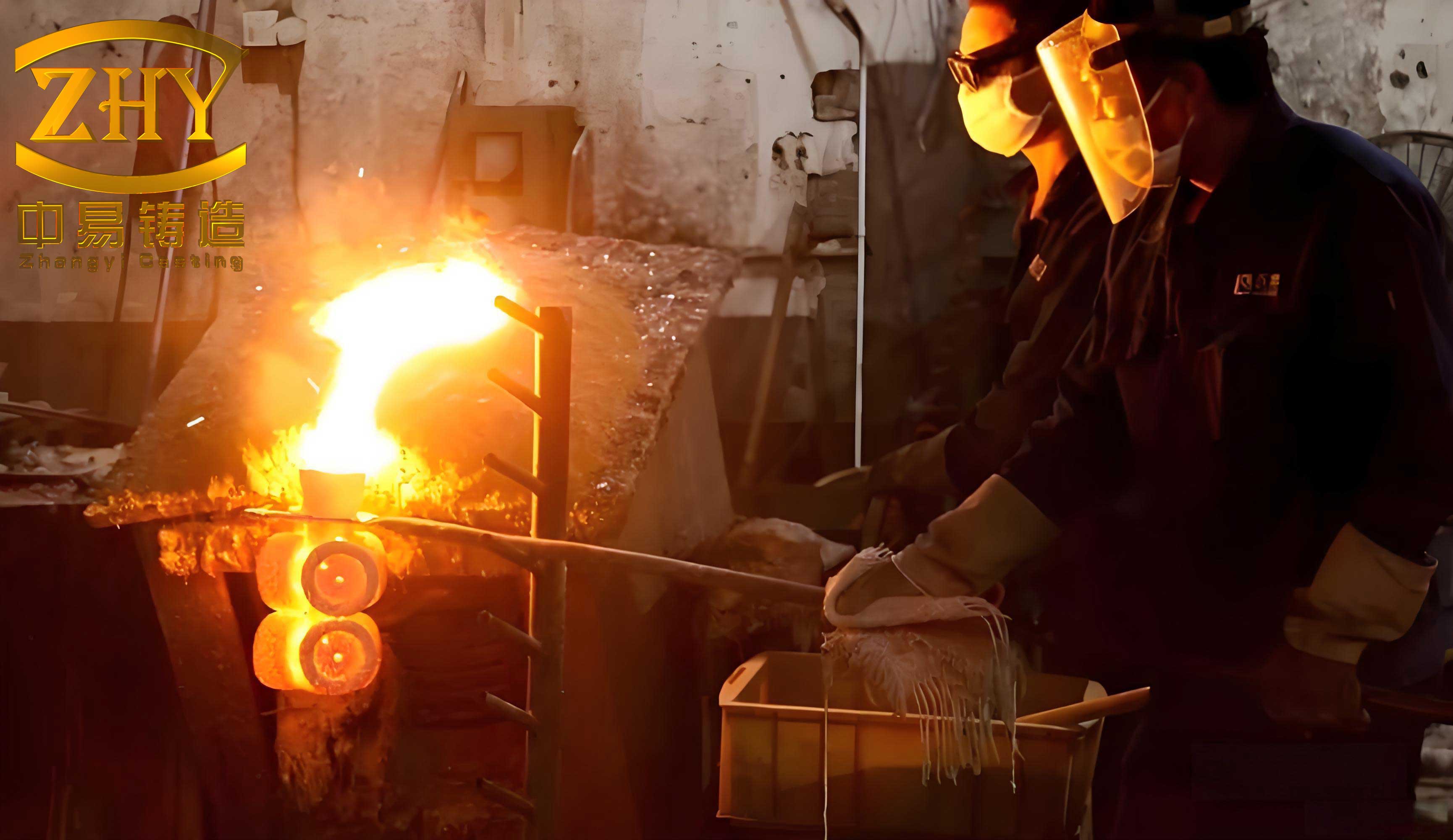
- Metal Pouring & Solidification: Molten iron at a precise temperature is poured into the preheated mold, which is often subjected to vibration to aid filling and degassing.
- Knock-out & Finishing: After cooling, the ceramic shell is removed, and the castings are separated from the gating system and finished.
The crux of quality lies in Step 4. The key parameters identified for intelligent control are:
• Pouring Temperature (Tp): $(1300 \pm 5)^{\circ}C$. Critical for fluidity and preventing premature solidification.
• Mold Preheat Temperature (Tm): ~$1100^{\circ}C$. Minimizes thermal shock and ensures proper filling.
• Liquid Metal Level in Furnace (L): Minimum threshold (e.g., 300L). Ensures sufficient material for a complete pour.
• Vibration Frequency (fv): $(40 \pm 3)$ Hz. Promotes mold filling, detrains entrapped air, and improves metallurgical density.
The schematic of the casting station is conceptually represented by a system comprising an induction melting/holding furnace, a pouring valve, the investment shell mold housed within upper and lower flask halves, and a three-axis vibration table. The intelligent control system orchestrates all these components.
Architecture of the PLC-Based Intelligent Control System
Control Philosophy and Workflow
The core objective is to maintain the key process variables within their optimal windows through real-time sensing and automated feedback control, replacing manual intervention and judgment. The PLC acts as the central brain. The control sequence is as follows:
1. System Initialization & Safety Check: Upon start command, the PLC verifies “home” positions of critical actuators (e.g., pouring valve is closed, mold flask is in locking position). Any deviation triggers an alarm and halts the cycle.
2. Temperature Ramp & Control: The induction furnace power is enabled. A laser pyrometer continuously measures the molten metal temperature $(T_{actual})$. This analog signal (4-20 mA) is read by the PLC’s Analog-to-Digital (A/D) module. The PLC compares $T_{actual}$ with the setpoint $T_{setpoint} = 1300^{\circ}C$.
3. Closed-Loop Temperature Adjustment: The error $e(t)$ is computed: $$e(t) = T_{setpoint} – T_{actual}(t)$$. A Proportional-Integral-Derivative (PID) algorithm within the PLC calculates the corrective output. This output is sent via a Digital-to-Analog (D/A) module as a 0-10V signal to a power regulator modulating the induction furnace’s input power. The control law can be simplified as:
$$u(t) = K_p e(t) + K_i \int_0^t e(\tau) d\tau + K_d \frac{de(t)}{dt}$$
where $u(t)$ is the control signal to the power regulator, and $K_p$, $K_i$, $K_d$ are tuning constants. This maintains $T_{actual}$ within $(1300 \pm 2)^{\circ}C$.
4. Level Monitoring: A laser-based level sensor monitors the furnace well. If level $L$ falls below the minimum threshold $L_{min}$, an alarm is raised, pausing the cycle until metal is replenished.
5. Vibration Control: When the temperature is stable and level is sufficient, the vibration table is activated. An accelerometer or vibration sensor measures the actual frequency $(f_{actual})$. The PLC compares this to the setpoint $(f_{setpoint}=40 Hz)$ and adjusts the output frequency of a Variable Frequency Drive (VFD) controlling the vibration motors, maintaining $(40 \pm 1.5)$ Hz.
6. Synchronized Pouring: With all parameters in the green band, the PLC commands the automated pouring valve to open for a pre-calculated duration, allowing a metered quantity of molten metal to fill the mold cavity while under controlled vibration.
7. Cooling & Reset: After pouring, a controlled cooling period is initiated before the mold is transferred. The system then resets, awaiting the next cycle.
The following table contrasts the traditional and PLC-controlled approaches:
| Feature | Traditional Manual Control | PLC-Based Intelligent Control |
|---|---|---|
| Temperature Control | Visual pyrometer reading, manual power adjustment. Prone to lag and overshoot. | Continuous laser sensing, PID-based closed-loop automatic adjustment. |
| Level Monitoring | Visual dip-stick or operator observation. High risk of under-pour. | Continuous non-contact laser monitoring with automatic low-level alarm/interlock. |
| Vibration Control | Fixed speed or manual potentiometer adjustment. Inconsistent between cycles. | Sensor feedback with real-time frequency adjustment via VFD for consistent amplitude. |
| Process Repeatability | Low, dependent on operator skill and attention. | High, governed by precise digital setpoints and algorithms. |
| Defect Prevention | Reactive, based on post-casting inspection. | Proactive, parameters are maintained within windows known to minimize defects. |
| Data Logging | Minimal or handwritten records. | Comprehensive digital traceability of all parameters for each casting cycle. |
Hardware Selection and System Configuration
The choice of hardware is critical for robustness and accuracy in the harsh foundry environment.
- PLC: A mid-range PLC (e.g., Mitsubishi FX3U series) is selected for its reliability, sufficient I/O capacity, and built-in communication ports. It executes the control logic, PID loops, and communicates with the HMI.
- Temperature Sensor: A short-wavelength (1 µm) infrared pyrometer (e.g., STL200 type) is essential. Standard long-wavelength (8-14 µm) sensors cannot see through the furnace’s observation glass. The 1 µm wavelength penetrates the glass, providing an accurate, non-contact measurement of the molten metal surface temperature.
- Level Sensor: A laser distance sensor configured for level measurement, providing a switch output at the low-level threshold and/or an analog signal for continuous monitoring.
- Vibration Sensor: An ICP/IEPE type accelerometer (e.g., CT1005LCICP) mounted on the vibration table provides a velocity or frequency proportional 4-20 mA signal.
- Power Actuation: A thyristor-based AC power regulator (e.g., controlled by MTAIS MT8 module) receives the 0-10V signal from the PLC’s D/A module to smoothly vary the induction furnace power.
- VFD: A standard industrial VFD controls the three-phase motors of the vibration table. Its speed reference is provided by the PLC’s analog output.
- HMI: A touch-screen panel (e.g., Weintek TK6070iP) serves as the operator interface for setpoint entry, real-time monitoring of trends, alarm display, and manual override.
The system’s signal flow can be modeled as a series of control loops. The primary temperature control loop’s block diagram is represented below, highlighting the role of the PLC:
Setpoint (Tsp) -> [Comparator] -> Error (e) -> [PLC PID Algorithm] -> Control Signal (u) -> [D/A Converter & Power Regulator] -> [Induction Furnace Plant] -> Molten Metal Temperature (T) -> [Laser Pyrometer & A/D Converter] -> (Feedback to Comparator)
The transfer function for the furnace plant is complex, but the PID tuning within the PLC effectively compensates for its dynamics to achieve zero steady-state error.
Design of the Control Program and Human-Machine Interface (HMI)
PLC Program Logic Structure
The PLC ladder logic and structured text program is designed around states and interlocks to ensure safe, sequential operation. The core flow is encapsulated in the following states:
- IDLE/INIT State: Waits for start command. Checks all safety interlocks (door closed, water flow OK, emergency stops reset).
- HOME CHECK State: Verifies actuator positions. If pouring valve is not closed or mold flask is not locked, it branches to an alarm routine and cannot proceed.
- HEATING State: Enables the furnace power control loop. The PID algorithm actively adjusts power to ramp and hold temperature. This state remains active until $|T_{setpoint} – T_{actual}| < \Delta T_{tolerance}$.
- READY-TO-POUR State: Entered when temperature is stable AND liquid level $L > L_{min}$. Activates the vibration table control loop to achieve and maintain $f_{setpoint}$.
- POURING State: Opens the pouring valve for a precise timer duration $t_{pour}$. Maintains vibration throughout. $$V_{pour} = \dot{Q} \cdot t_{pour}$$ where $V_{pour}$ is the volume poured and $\dot{Q}$ is the calibrated flow rate.
- SOLIDIFICATION State: Closes the pouring valve but maintains vibration for a post-pour duration $t_{post-vibe}$ (e.g., 180 seconds) to aid feeding. Then stops vibration and initiates a cooling timer.
- COMPLETE State: Signals the material handling system to remove the filled mold. Resets all outputs and returns to IDLE/INIT state.
Alarm routines are embedded at every stage. For instance, if the level drops during the READY-TO-POUR state, an immediate alarm is triggered, the pour is aborted, and the system enters a safe HOLD state.
HMI Screen Design for Monitoring and Control
The HMI provides visualization and interaction. Key screens include:
1. Main Process Overview: A mimic diagram showing the furnace, valve, mold, and vibration table with real-time animated status (on/off, open/closed). Key live values are displayed: $T_{actual}$, $L$, $f_{actual}$.
2. Trend Display: Multi-pen trend charts plotting $T_{actual}$, $f_{actual}$, and control output signals over time for the current and previous cycles, crucial for process analysis and PID tuning.
3. Parameter Setting Screen: Password-protected screens for engineers to input setpoints and tolerances:
| Parameter | Symbol | Setpoint Range | Default Value | Tolerance |
|---|---|---|---|---|
| Pouring Temperature | $T_{setpoint}$ | 1100 – 1500 °C | 1300 °C | ±5 °C |
| Vibration Frequency | $f_{setpoint}$ | 5 – 100 Hz | 40 Hz | ±3 Hz |
| Minimum Furnace Level | $L_{min}$ | 50 – 2500 L | 300 L | Alarm Only |
| Pouring Time | $t_{pour}$ | 1.0 – 15.0 s | Calculated | N/A |
| Post-Pour Vibration Time | $t_{post-vibe}$ | 60 – 300 s | 180 s | N/A |
4. Alarm History Log: A time-stamped list of all alarms (e.g., “Low Level Alarm – 14:32:05”, “Temperature Deviation High – 14:28:11”), essential for troubleshooting and maintenance.
The HMI trend display is particularly powerful for the lost wax investment casting process. Operators can observe the temperature stability during the hold period before the pour, ensuring the metal is neither too hot (risking gas absorption) nor too cool (risking misruns). The vibration frequency plot confirms consistent dynamic conditions for each casting.
System Performance and Results
The implementation of the PLC-based intelligent control system for lost wax investment casting led to measurable improvements in process stability and product quality.
1. Enhanced Parameter Stability: The closed-loop control drastically reduced the variance in key parameters.
- Temperature Control: Manual control often resulted in variations exceeding ±10°C. The PID-controlled system consistently maintained temperature within ±2°C of the 1300°C setpoint. The standard deviation of pouring temperature $(σ_T)$ decreased from approximately 4.5°C to 0.8°C.
- Vibration Control: Vibration frequency was stabilized. The control algorithm adjusted the VFD output $V_{DA}$ based on the error: $$f_{actual} = K \cdot (V_{DA} – V_{offset})$$ where $K$ is a gain constant. This maintained $f_{actual}$ at $40 \pm 1.5$ Hz, compared to swings of up to ±8 Hz with manual control.
- Level Assurance: The low-level interlock completely eliminated under-pour incidents caused by human oversight.
2. Reduction in Casting Defects: The consistency in process parameters directly correlated with a lower scrap rate. Defects primarily associated with temperature and filling irregularities were reduced.
| Defect Type | Approximate Rate (Manual Control) | Approximate Rate (PLC Control) | Primary Parameter Addressed |
|---|---|---|---|
| Misrun / Cold Shut | 3.2% | 0.7% | Pouring Temperature, Mold Preheat |
| Shrinkage Porosity | 2.1% | 0.9% | Pouring Temperature, Vibration |
| Inclusions (Slag) | 1.8% | 1.5% | Consistent Pouring Practice |
| Total Scrap Rate | ~7.1% | ~3.1% | All Controlled Parameters |
3. Operational and Economic Benefits:
- Repeatability: Every brake disc is now cast under nearly identical conditions, leading to more uniform mechanical properties (hardness, tensile strength) across production batches.
- Reduced Skill Dependency: The system reduces reliance on highly skilled furnace operators for critical judgments, allowing them to focus on overall system supervision and maintenance.
- Predictive Maintenance: Trend data from the HMI can reveal gradual changes, such as declining heating efficiency or changing vibration characteristics, signaling the need for maintenance before failure.
- Energy Efficiency: Precise temperature holding eliminates unnecessary overheating and reduces holding power consumption.
The intelligent control system transforms the lost wax investment casting station from an open-loop, skill-based process into a closed-loop, data-driven manufacturing cell. The PLC’s deterministic control and the HMI’s visibility provide a foundation for Industry 4.0 integration, where data can be fed into plant-wide MES (Manufacturing Execution Systems) for full traceability and advanced analytics.
Conclusion and Future Outlook
The development and deployment of a PLC-based intelligent control system for the lost wax investment casting of automotive brake discs have demonstrated significant advantages. By focusing on the real-time, closed-loop control of pouring temperature, metal level, and vibration frequency—the most influential parameters for casting integrity—the system ensures process stability and repeatability that is unattainable through manual operation. The integration of specialized sensors (short-wave pyrometer, laser level gauge) with robust PLC logic and an informative HMI creates a cohesive platform that not only automates tasks but also provides deep process insight.
The results speak clearly: a dramatic reduction in parameter variance, a consequent drop in defect-related scrap rates, and the establishment of a digital record for each casting cycle. This approach elevates the capability of the lost wax investment casting process, making it more competitive for high-volume, quality-critical components like brake discs.
Future enhancements to this system could involve:
• Integrating mold temperature monitoring via infrared cameras to close the loop on mold preheat.
• Implementing advanced control algorithms like Model Predictive Control (MPC) to further optimize the thermal ramp and pour profile.
• Adding machine vision for automated inspection of the wax pattern or final casting directly at the station.
• Connecting the PLC to a cloud-based platform for remote monitoring, predictive quality modeling, and seamless integration with smart factory networks.
In conclusion, the application of programmable automation and intelligent control principles to lost wax investment casting is a pivotal step towards achieving zero-defect manufacturing in the foundry industry, ensuring that critical safety components like automotive brake discs are produced with unwavering quality and reliability.