
My investigation focuses on the fundamental characteristics of carbides within various types of white cast iron. In gray and ductile irons, carbon primarily exists as graphite, and a change from flake to spheroidal graphite leads to a dramatic improvement in properties. Conversely, in white cast iron, carbon is mainly combined as hard carbides. A transition in the carbide type, for instance from the orthorhombic M3C type to the hexagonal M7C3 type, is known to significantly enhance wear resistance and toughness. Despite this importance, detailed and comparative studies on the three-dimensional structure and morphology of carbides in plain white cast iron, Ni-Hard iron, high-chromium white cast iron, and boron-alloyed white cast iron remain limited. This work aims to systematically explore and elucidate these aspects.
I. Methodology and Experimental Procedures
The core of this experimental approach involved revealing the true three-dimensional architecture of the carbide phase. This was achieved through specialized deep-etching techniques that selectively remove the metallic matrix, leaving the carbide network intact for observation.
1.1 Material Specifications
Four distinct types of white cast iron were prepared for this study. Their chemical compositions, which are critical in determining the resulting carbide type and morphology, are detailed in Table 1.
| Sample Type | C | Si | Mn | Cr | Ni | B | Fe |
|---|---|---|---|---|---|---|---|
| Plain White Cast Iron | ~3.0 | <1.0 | <1.0 | – | – | – | Bal. |
| Ni-Hard Type I | ~2.8 | <0.8 | <0.8 | ~1.8 | ~4.5 | – | Bal. |
| High-Chromium Cast Iron | ~2.6 | <1.0 | <1.0 | ~20.0 | – | – | Bal. |
| Boron White Cast Iron | ~3.2 | <1.5 | <1.0 | ~3.0 | – | ~1.5 | Bal. |
Table 1: Nominal chemical composition of the investigated white cast iron samples (wt.%).
1.2 Electrolytic Deep-Etching Technique
To expose the carbide skeleton, an electrolytic deep-etching process was employed. Different electrolytes and parameters were optimized for each type of white cast iron to ensure clean removal of the matrix while preserving the delicate carbide structure. The specific conditions are summarized in Table 2.
| Sample | Electrolyte Composition | Current Density (mA/cm²) | Time (s) | Temperature (°C) | Preserved Phase |
|---|---|---|---|---|---|
| Plain White Iron | 10% HCl in Methanol | 50 | 30-60 | 20-25 | Carbide |
| Ni-Hard Iron | 10% HNO3 in Methanol | 100 | 20-40 | <10 | Carbide |
| High-Cr Iron | 10% HCl + 1% Tartaric Acid in Methanol | 80 | 40-80 | 20-25 | Carbide |
| Boron White Iron | 5% HCl + 5% Glycerol in Methanol | 60 | 50-100 | 20-25 | Carbide |
Table 2: Electrolytic deep-etching parameters for revealing carbide morphology in different white cast irons.
1.3 Analytical Equipment
The etched samples and polished metallographic specimens were analyzed using a suite of advanced techniques:
- Scanning Electron Microscopy (SEM): Used for high-resolution imaging of the three-dimensional carbide morphology from deep-etched samples and the two-dimensional microstructure.
- X-ray Diffractometry (XRD): Employed for phase identification and determining the crystal structure of the carbides in each type of white cast iron.
- Electron Probe Microanalysis (EPMA) / Energy Dispersive Spectroscopy (EDS): Utilized for microchemical analysis to determine the distribution and partitioning of alloying elements (e.g., Cr, B) between the carbides and the matrix.
- Secondary Ion Mass Spectrometry (SIMS): Specifically applied to map the distribution of boron in the boron-alloyed white cast iron.
II. Analysis of Carbide Crystal Structure
The crystal structure of the carbide phase is the primary factor distinguishing the properties of different white cast irons. XRD analysis was definitive in this identification.
2.1 Plain and Ni-Hard White Cast Iron
The XRD patterns for both plain white cast iron and Ni-Hard cast iron were consistent with the orthorhombic cementite structure. The diffraction peaks matched those of Fe3C (PDF card). For the Ni-Hard white cast iron, microchemical analysis via EPMA revealed a strong partitioning of chromium into the carbide phase. The distribution coefficient for Cr, $k_{Cr}$, defined as the ratio of its concentration in the carbide to that in the matrix, was significantly greater than 1:
$$k_{Cr} = \frac{C_{Cr}^{carbide}}{C_{Cr}^{matrix}} \gg 1$$
This is expected due to the similarities between chromium and iron: comparable atomic radii (Cr: ~1.28 Å, Fe: ~1.26 Å), similar electronegativity (Cr: 1.66, Fe: 1.83), and identical cubic crystal structure. Chromium therefore readily substitutes for iron in the cementite lattice, forming an alloyed carbide best represented as (Fe,Cr)3C. The lattice parameters can be expressed as a function of chromium content, generally following Vegard’s law for solid solutions: $a = a_{Fe_3C} + \alpha x_{Cr}$, where $a_{Fe_3C}$ is the lattice parameter of pure iron carbide and $\alpha$ is a constant.
2.2 High-Chromium White Cast Iron
The XRD pattern for the high-chromium white cast iron sample was distinctly different. The primary set of diffraction peaks corresponded unequivocally to the hexagonal M7C3-type carbide, specifically (Cr,Fe)7C3. This transition from M3C to M7C3 is the key metallurgical change imparted by high chromium levels (typically >12%), leading to improved toughness and wear resistance. The crystal structure is more complex than cementite, with a typical unit cell containing 28 metal atoms and 12 carbon atoms.
2.3 Boron-Alloyed White Cast Iron
The XRD analysis of the boron white cast iron revealed a multi-phase carbide structure. The pattern indicated the presence of not just one, but several carbides: Fe3(C,B), Fe23(C,B)6, and some M7C3. SIMS and EPMA analysis confirmed that both chromium and boron were heavily concentrated within the carbide phases. Boron, with an atomic radius (~0.85 Å) similar to carbon (~0.77 Å), an electronegativity (2.04) close to carbon (2.55), and a hexagonal crystal structure (like M7C3), can substitute for carbon in various carbide lattices. This leads to the formation of complex borocarbides. The general formula for these phases can be considered as Mx(C1-yBy)z, where ‘M’ is primarily Fe and Cr, and ‘y’ represents the degree of boron substitution for carbon.
The identified carbide structures for each white cast iron are conclusively summarized in Table 3.
| Type of White Cast Iron | Primary Carbide Phase(s) | Crystal System |
|---|---|---|
| Plain White Cast Iron | Fe3C (Cementite) | Orthorhombic |
| Ni-Hard Cast Iron | (Fe,Cr)3C (Alloyed Cementite) | Orthorhombic |
| High-Chromium Cast Iron | (Cr,Fe)7C3 | Hexagonal |
| Boron White Cast Iron | Fe3(C,B), Fe23(C,B)6, (Cr,Fe)7C3 | Orthorhombic, Cubic, Hexagonal |
Table 3: Summary of carbide phases identified in the investigated white cast irons.
III. Three-Dimensional Morphology of Carbides
While the crystal structure defines the hardness and stability, the three-dimensional morphology of the carbide network dictates the fracture path and overall toughness of the white cast iron. Observations from deep-etched samples provided profound insights.
3.1 Plain and Ni-Hard White Cast Iron
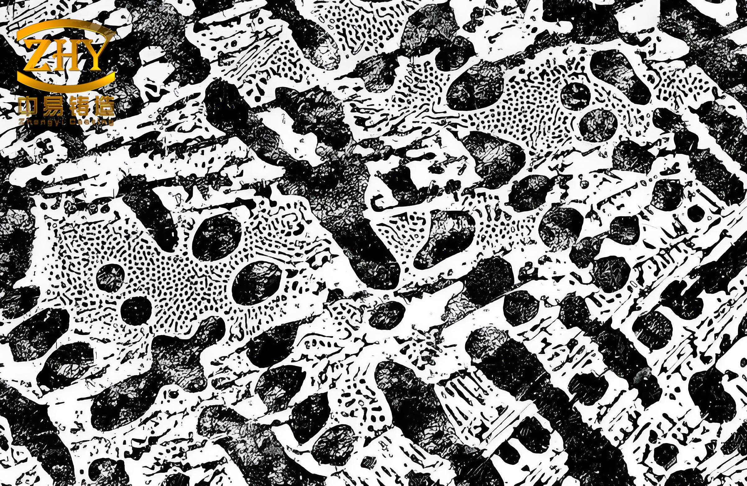
Metallographic examination of plain white cast iron showed a continuous network of carbide surrounding islands of pearlite. SEM observation of deep-etched samples revealed this network in its true form: a honeycomb-like, fully interconnected skeleton. When the observation plane was tilted or when viewing a fractured edge, it became clear that this carbide network was a continuous, fully enclosed three-dimensional lattice. The metallic matrix (pearlite) existed as discrete, isolated volumes trapped within this lattice. The Ni-Hard white cast iron exhibited a very similar morphology, albeit with a slightly finer and somewhat thinner carbide web due to the moderate chromium addition, but it remained a fully continuous and enclosed skeleton. Based on these observations, a three-dimensional schematic model for the microstructure of these M3C-type white cast irons can be conceptualized as a fully connected, space-filling carbide cage.
2.2 High-Chromium White Cast Iron
The microstructure of high-chromium white cast iron was markedly different in two dimensions, showing isolated, blocky, or rod-like carbides, often in a “eutectic colony” or “rosette” pattern. However, three-dimensional analysis through deep-etching told a more nuanced story. The carbides were not completely isolated particles. Instead, they were interconnected, forming an open, three-dimensional skeleton. This skeleton retained the characteristic faceted, rod-like, or blade-like growth habit of the M7C3 carbide crystals. The skeletal network was extensive but not fully enclosing; it presented a more open framework compared to the dense cage of M3C carbides. This open structure provides a continuous but less brittle pathway for crack propagation and allows for a more contiguous metallic matrix, explaining the superior toughness of this type of white cast iron.
2.3 Boron-Alloyed White Cast Iron
The boron white cast iron, especially after modification with rare earth and aluminum, displayed a mixed morphology. The carbides appeared as a combination of blocky particles and an interconnected, but broken or discontinuous, network. Deep-etching confirmed this intermediate state. The carbide phase formed a three-dimensional skeleton that was more connected and complex than the open skeleton of high-chromium iron but less continuous and fully enclosing than the skeleton in plain or Ni-Hard white cast iron. It featured regions of local enclosure connected by thinner links, resulting in a partially discontinuous network. This structure is attributed to a divorced eutectic solidification mode promoted by the modifiers, where the carbide grows in a more discrete manner rather than forming a fully coupled eutectic network.
The key morphological characteristics are compared in Table 4.
| Type of White Cast Iron | 2D Metallographic Appearance | 3D Carbide Morphology | Connectivity & Enclosure |
|---|---|---|---|
| Plain / Ni-Hard | Continuous network, honeycomb ledeburite | Fully enclosed, space-filling lattice | Continuous phase (matrix is isolated) |
| High-Chromium | Isolated rods/blocks, eutectic rosettes | Open, interconnected skeleton | Interconnected, but matrix is also continuous |
| Boron-Alloyed | Blocky + broken network | Partially enclosed, discontinuous skeleton | Semi-continuous, intermediate state |
Table 4: Comparative analysis of carbide morphology in different white cast irons.
IV. Schematic Models and Discussion
Synthesizing the structural and morphological findings, schematic three-dimensional models can be proposed to visualize the fundamental differences. For high-chromium white cast iron, the model depicts rod-like M7C3 carbides originating from central nuclei within a eutectic colony, growing radially and connecting with neighboring rods to form an open, three-dimensional framework. The metallic matrix fills the interstices of this open framework.
For the plain and Ni-Hard white cast irons, the model is that of a highly complex, multiply-connected lattice or cage. The carbide phase forms the walls of this cage, creating completely isolated cells that are filled with the metallic matrix phase (e.g., pearlite, martensite). The boron white cast iron model is intermediate, showing interconnected carbide blocks and segments that form a network with frequent breaks or discontinuities, leading to a mixture of isolated and interconnected matrix regions.
The overarching conclusion is that in all forms of white cast iron, the carbide phase forms a three-dimensional skeletal structure. The critical difference lies in the degree of continuity and enclosure of this skeleton. This continuum ranges from a fully closed, continuous cage (M3C-type) to an open framework (M7C3-type), with modified structures like the boron-alloyed white cast iron occupying an intermediate position. This morphological gradient directly correlates with the mechanical property gradient, particularly toughness and crack propagation resistance, observed across the family of white cast iron alloys. The transition in white cast iron from a brittle, fully continuous carbide network to a tougher, more open skeleton represents a fundamental microstructural design principle for engineering wear-resistant materials.