
In my extensive experience working with aluminum castings, particularly in the aerospace sector, I have encountered numerous challenges related to defect formation. One of the most persistent and critical issues has been the occurrence of slag inclusions in large, structurally complex castings. This article delves deep into the problem of slag inclusions in skeleton-type aluminum castings, drawing from hands-on analysis and process improvements. Slag inclusions, often stemming from turbulent flow and oxidation during pouring, can severely compromise the mechanical integrity and fatigue life of components subjected to harsh operational environments, such as intense vibration. Through this first-person account, I aim to elucidate the root causes, explore analytical methods using fluid dynamics principles, and present a robust solution that has proven effective in practical foundry settings.
The casting in question is a large skeletal component, characterized by an I-beam-like geometry with significant dimensional scales. Key structural features include upper and lower flanges connected by a thin, expansive web. The maximum overall dimensions approximate 350 mm in width, 428 mm in depth, and 682 mm in height. Wall thicknesses vary considerably: the flanges are around 22 mm thick, the web is a mere 12 mm, and localized masses, such as reinforced lifting points, can reach up to 50 mm. Manufactured from ZL104 aluminum-silicon alloy, the casting has a net weight of approximately 40 kg. Given its role as a primary load-bearing element under dynamic vibratory loads, quality standards are exceptionally high, mandating 100% radiographic inspection per stringent aerospace classifications. Initial production attempts were plagued by pervasive slag inclusions, primarily located in the lower flange and web regions, necessitating a comprehensive re-evaluation of the gating and pouring methodology.
The foundational production conditions established for this casting are typical for high-quality aluminum foundry work. Melting of the ZL104 alloy is conducted in a 500 kg capacity resistance furnace. Refinement is achieved using hexachloroethane (C₂Cl₆) as a degassing and cleansing agent, while modification of the eutectic silicon structure is performed with a proprietary two-color modifier block added at about 1% of the molten metal weight. Standard melting practices are followed to ensure adequate temperature control and chemical homogeneity. The pouring temperature is maintained within the range of 710°C to 730°C to balance fluidity and minimize gas solubility. Molding employs oil-sand cores for the principal cavity, backed by green sand molds made from clay-bonded silica sand with a grain fineness of approximately 70/140. All molding is done manually, which introduces variability that must be accounted for in process design.
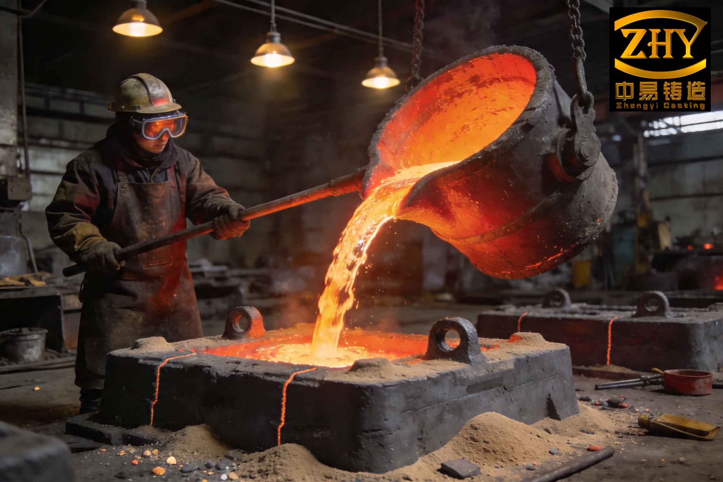
The core of the problem lies in the interaction between the casting geometry and the dynamics of molten metal flow. Slag inclusions in these castings are not random; they exhibit a distinct pattern, consistently appearing in the lower flange and the mid-to-lower sections of the thin web. This regularity points unequivocally to the gating system’s design as the primary culprit. To understand this, we must analyze the initial gating schemes employed. Two primary designs were used initially, both centered on a vertical slot gate system intended to feed the large web area smoothly. The first design, a direct drop system, featured a tall sprue leading directly to an inclined runner that fed the slot gate. The second design introduced a buffer step—a horizontal runner at an intermediate height—before the inclined runner and slot gate.
The severe formation of slag inclusions can be attributed to the excessive kinetic energy and turbulent flow generated during the initial stages of pouring. When molten aluminum falls freely over a large vertical drop, its velocity at impact can be calculated using Torricelli’s law for free-falling fluids. For a drop height \( h \), the impact velocity \( v \) is given by:
$$ v = \sqrt{2gh} $$
where \( g \) is the acceleration due to gravity (approximately \( 9.81 \, \text{m/s}^2 \)). In the direct drop design, the total fall from the pouring cup to the entry of the inclined runner was about 900 mm. Substituting into the formula:
$$ v = \sqrt{2 \times 9.81 \, \text{m/s}^2 \times 0.9 \, \text{m}} \approx \sqrt{17.658} \, \text{m/s} \approx 4.2 \, \text{m/s} $$
This high velocity, equivalent to 4200 mm/s, results in a powerful impingement on the inclined runner surface. This impact causes severe splashing and vortex formation, particularly at the root of the inclined channel. The intense turbulence leads to extensive air entrainment and reaction with the melt, generating substantial secondary oxide films—the primary source of slag inclusions. These oxides, along with any eroded mold sand, are then carried into the mold cavity. Once inside, the geometry hinders their removal. The lower flange’s curved surface and intricate ribbing act as traps, while the thin web (12 mm) solidifies rapidly, preventing buoyant ascent and separation of the slag inclusions before the metal sets.
The stepped buffer design reduced the direct drop to about 600 mm, lowering the impact velocity and subsequent turbulence. However, the inclined runner section remained a significant source of vortex-driven slag inclusion formation. Radiographic inspection data from the initial production batches clearly quantified the difference. The table below summarizes the findings from the two initial gating systems, highlighting the correlation between gating design and the severity of slag inclusions.
| Gating System Design | Number of Castings Produced | Primary Slag Inclusion Locations | Severity Index (Qualitative) | Key Flow Issue |
|---|---|---|---|---|
| Direct Drop (Scheme A) | 12 | Lower Flange & Entire Web | High / Severe | High-velocity impact, severe splashing & vortex in inclined runner. |
| Stepped Buffer (Scheme B) | 6 | Primarily Lower Flange | Moderate | Reduced initial drop, but persistent vortex in inclined runner. |
The analysis confirms that the fundamental cause of the pervasive slag inclusions was the inadequate buffering and calming of the metal stream before it entered the critical slot gate and mold cavity. The initial systems failed to sufficiently dissipate the kinetic energy gained from the tall sprue, leading to sustained turbulence and oxidation. This problem is exacerbated in aluminum alloys like ZL104, which are particularly prone to forming tenacious oxide films that readily become entrapped as slag inclusions.
To mitigate these issues, a completely redesigned gating system was conceived and implemented. The primary objective was to achieve a quiescent, non-turbulent flow into the mold cavity by employing a multi-stage flow restriction and filtration strategy. The new design is a compound system integrating a conical sprue, an extended horizontal runner with a filter, a serpentine (labyrinth) channel, a second filter within a vertical spruce/riser, and finally, the vertical slot gates attached to the casting’s web. This compound chink gating system is illustrated conceptually in the discussion below.
The key modifications and their functions are as follows:
- Conical Sprue: Two conical sprues with a top diameter of approximately 18 mm and a bottom diameter of 16 mm replace the previous cylindrical sprues. The tapered shape promotes a smoother, more cohesive flow with reduced air aspiration.
- High-Placed Horizontal Runner: The main horizontal runner is positioned at the highest practical point on the pattern, at the mold parting line, approximately 650 mm below the pouring cup. This placement immediately reduces the effective fall height. The runner cross-section is enlarged to 30/40 mm x 50 mm (tapered) to act as a primary settling basin.
- Primary Ceramic Foam Filter: A ceramic foam filter with a pore size suitable for aluminum is placed within the horizontal runner. This filter intercepts initial dross and slag inclusions generated in the sprue and runner, while also disrupting flow to reduce velocity.
- Serpentine (Labyrinth) Channel: Following the horizontal runner, the metal enters a serpentine channel with a circular cross-section of about 25 mm diameter. This channel’s tortuous path forces multiple directional changes, effectively dissipating kinetic energy and calming the stream through repeated momentum loss. The pressure drop \( \Delta P \) through such a channel can be approximated by a sum of major and minor losses:
$$ \Delta P = f \frac{L}{D} \frac{\rho v^2}{2} + \sum K \frac{\rho v^2}{2} $$
where \( f \) is the Darcy friction factor, \( L \) and \( D \) are the length and diameter of the pipe, \( \rho \) is the fluid density, \( v \) is the mean velocity, and \( K \) represents loss coefficients for bends. This design ensures the velocity \( v \) entering the next stage is minimal.
- Vertical Riser/Spruce with Secondary Filter: The calmed metal from the serpentine channel enters a vertical spruce, which also functions as a riser. A second ceramic foam filter is placed at the entrance to this spruce. This provides a final, critical cleaning stage, capturing any remaining slag inclusions before the metal enters the mold cavity proper.
- Vertical Slot Gates: The metal finally flows from the spruce into the traditional vertical slot gates attached to both sides of the casting’s web. By this stage, the velocity is very low, and the flow is essentially laminar, ensuring a gentle, wave-like filling of the thin web section.
The area ratios for this compound gating system were carefully calculated to ensure progressive flow restriction and adequate feeding. The ratio is as follows, where \( F \) denotes cross-sectional area:
$$ F_{\text{sprue}} : F_{\text{runner}} : F_{\text{serpentine}} = 4 : 35 : 10 \approx 1 : 8.75 : 2.5 $$
This ratio ensures the runner is sufficiently large to act as a reservoir and slag trap, while the serpentine provides the necessary flow resistance.
The efficacy of this new system was validated through production. A batch of 24 castings was produced using the compound gating design. Radiographic inspection revealed a complete elimination of significant slag inclusions. All castings met the required Class II specification without any defects in the lower flange or web sections. The success of this approach provides several generalizable insights for producing large, thin-walled aluminum castings prone to slag inclusions.
First, the principle of stepped energy dissipation is paramount. For tall castings, a single buffer is often insufficient. Employing multiple stages—such as a horizontal runner followed by a serpentine channel—creates a cumulative calming effect. The use of the horizontal runner as a primary settling basin is crucial. Its large surface area allows for buoyant separation of some lighter slag inclusions even before the filter, as described by Stokes’ law for the terminal velocity \( v_t \) of a spherical particle in a fluid:
$$ v_t = \frac{2}{9} \frac{(\rho_p – \rho_f) g r^2}{\eta} $$
where \( \rho_p \) and \( \rho_f \) are the particle and fluid densities, \( r \) is the particle radius, and \( \eta \) is the dynamic viscosity. A larger, quieter runner provides the residence time needed for this separation to occur, reducing the load on the downstream filters.
Second, strategic filter placement is a non-negotiable element for high-integrity castings. The dual-filter system in this design serves complementary roles. The first filter in the runner handles the initial, most severe contamination from the sprue. The second filter acts as a final polish. The pressure drop across a ceramic foam filter also contributes to flow calming. The inclusion of filters must be planned meticulously; they should be placed in locations where metal velocity is already reduced to prevent erosion of the filter material itself, which could generate new slag inclusions.
Third, the complete avoidance of inclined runners or any channel that promotes vortex formation is recommended. Inclined planes can cause metal to cascade and fold over itself, entrapping air and oxides. The serpentine channel, with its uniform cross-section and designed bends, is a superior alternative for achieving controlled deceleration without inducing uncontrolled rotational flow that leads to slag inclusions.
To further generalize the findings, the following table contrasts the characteristics of problematic and optimized gating elements concerning slag inclusion formation in aluminum castings.
| Gating Element | Problematic Design (Promotes Slag Inclusions) | Optimized Design (Minimizes Slag Inclusions) | Key Principle |
|---|---|---|---|
| Sprue | Straight cylindrical, large drop height. | Tapered (conical), minimized effective drop via intermediate runners. | Reduce entry velocity and air aspiration. |
| Primary Runner | Small cross-section, placed low, direct connection to gates. | Large cross-section, placed high, acts as a settling basin, includes filter. | Provide residence time for buoyant separation and initial filtration. |
| Flow Channel to Gate | Inclined runner or direct drop. | Serpentine/labyrinth channel or vertical chute. | Dissipate kinetic energy through friction and directional changes. |
| Gate Inlet | Unfiltered, high-velocity stream. | Filtered, low-velocity stream from a calming zone (e.g., riser). | Final cleaning and stabilization of flow before cavity entry. |
| Overall System Goal | Rapid filling, minimal attention to flow regime. | Controlled, quiescent, laminar filling front progression. | Prevent turbulence, air entrainment, and surface oxide folding. |
The discussion would be incomplete without considering the metallurgical factors. The propensity for slag inclusion formation is also influenced by melt quality. Even with an optimal gating system, a dirty melt will yield defective castings. Therefore, the gating design must be part of an integrated approach that includes rigorous melt treatment. The effectiveness of hexachloroethane degassing, for instance, can be modeled by considering the rate of gas bubble removal. The number of slag inclusion nuclei \( N \) present after a treatment time \( t \) can be related to initial inclusion count \( N_0 \) and a removal rate constant \( k \) influenced by bubble flux and coalescence:
$$ N = N_0 e^{-kt} $$
Effective gating preserves this clean melt state by preventing re-oxidation and slag pick-up during the transfer into the mold.
In conclusion, the investigation into slag inclusions for large skeleton-type aluminum castings yields definitive guidelines. The root cause was the inadequate gating system that allowed high-velocity, turbulent flow to generate and carry secondary oxides into the mold cavity. The solution was a compound gating system featuring a high horizontal runner, a serpentine calming channel, and strategically placed dual ceramic foam filters, all feeding a vertical slot gate. This design successfully transformed the metal flow from a destructive, high-energy jet into a gentle, laminar fill, thereby eliminating the slag inclusion defect. The principles established—multi-stage buffering, mandatory filtration, and avoidance of turbulence-inducing features like inclined runners—are broadly applicable to the production of any large, complex aluminum casting where slag inclusions pose a significant quality risk. Future work could involve computational fluid dynamics (CFD) simulations to further optimize the dimensions of the serpentine channel and filter placements for different casting geometries, but the empirical success of this compound system underscores its practical viability in foundry operations aimed at achieving zero-defect production of critical components.