
Investment casting can produce thin-walled stainless steel components with complex internal and external geometry, but the process becomes difficult when thin sections, heavy junctions, and dimensional requirements occur in the same part. A bearing seat used in food-processing equipment illustrates the problem. The part is made from 1.4308 stainless steel (GX5CrNi19-10), an austenitic grade with good corrosion resistance and toughness. Its maximum envelope is 245 mm × 214 mm, the cylindrical barrel is about 245 mm long, and the as-cast wall thickness is 5–6 mm. After machining, the barrel ends are reduced to about 3 mm. The part also has a 2.4 mm thick protruding plate, a 1.8 mm thin inner web, and 2.5 mm reinforcing ribs. The total casting mass is 2.2 kg. Functional requirements include flatness at the frame bosses, coaxiality at the barrel, and flatness at the lower protruding plate. Internal shrinkage porosity is not acceptable, and surface shrinkage, scarring, or distortion can make the casting unusable.
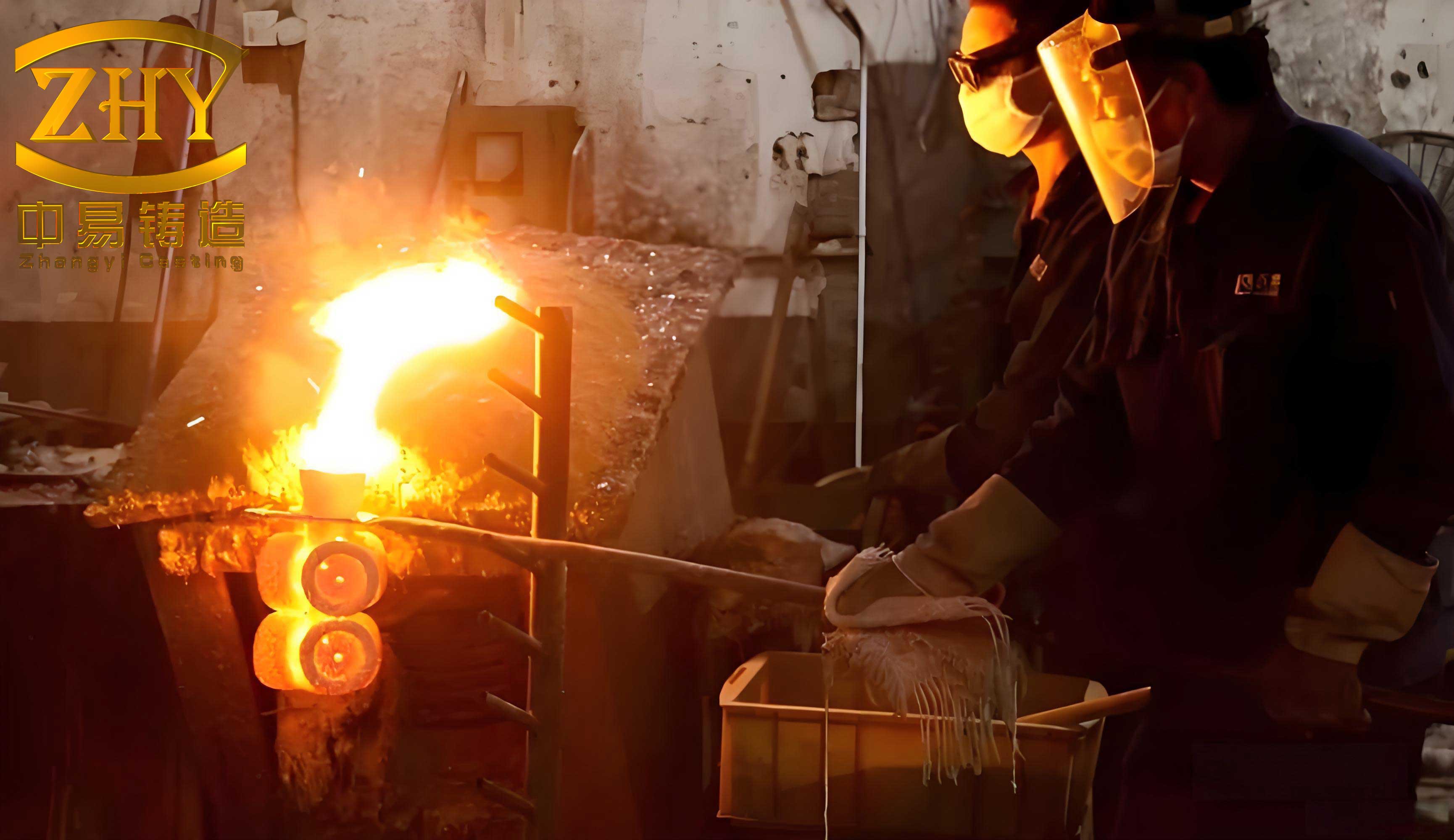
In production, the bearing seat suffered from shrinkage porosity, misrun, and scarring, and the qualified yield was low. The technical challenge is not simply “adding more metal” or “raising the pouring temperature.” Thin walls require rapid filling before the metal freezes, while thick junctions require sufficient liquid metal and a positive feeding path during solidification. Those two requirements conflict. The process development therefore combined gating-system design, finite-element simulation, orthogonal experimentation, and a neural-network surrogate with a genetic algorithm to search for improved process parameters.
Process Configuration and Five Gating Designs
The alloy has a simulated solidus of 1386 °C and a liquidus of 1485 °C. The initial process used a pouring temperature of 1620 °C, a shell preheat temperature of 1130 °C, a shell thickness of 6 mm, and a gravity pouring rate of 2 kg·s−1. The investment shell used a zircon sand face layer, mullite backup layers, and a silica-sol binder. Wax patterns were assembled on a central sprue, dewaxed by steam, and the shells were preheated for at least 1.5 h before pouring. Cooling was by air. The simulation model used a symmetric half-section, a 2 mm element size on the bearing seat, 4 mm on the gating system, and a 6 mm shell. A consistent interface with a heat-transfer coefficient of 500 W/(m²·K) was assigned between the metal and the shell.
The ingates were placed on the thin cylindrical barrel and on one side of the rectangular frame to promote filling of the thinnest sections. Five gating configurations were compared: a horizontal barrel with the thin plate at the bottom; a vertical barrel with the plate at one side and step pouring; an inclined large-plane arrangement; a horizontal barrel with the plate on top and combined bottom and side feeding; and a four-cavity version with a vertical barrel and multiple ingates. The configurations differed in module mass, casting yield, and predicted shrinkage location.
| Scheme | Pouring position and gating concept | Cavities | Module mass (kg) | Yield (%) | Simulated shrinkage volume (cm³) | Simulated shrinkage locations |
|---|---|---|---|---|---|---|
| 1 | Horizontal barrel, thin plate at bottom; single sprue with side ingates | 2 | 9.9 | 44.4 | 0.71 | 14 |
| 2 | Vertical barrel, thin plate at side; multiple sprues, step pouring | 2 | 11.6 | 37.9 | 0.76 | 16 |
| 3 | Horizontal barrel, thin plate inclined; single sprue, inclined pouring | 2 | 10.2 | 43.1 | 0.76 | 15 |
| 4 | Horizontal barrel, thin plate on top; combined bottom and side feeding | 2 | 10.4 | 42.3 | 0.84 | 12 |
| 5 | Vertical barrel, thin plate at side; single sprue with multiple ingates | 4 | 18.0 | 48.9 | 0.76 | 14 |
Filling, Solidification, and Defect Formation
All five designs filled the bearing seat without complete premature freezing in the simulation, but the filling patterns were not equivalent. Schemes 3 and 4 showed local splashing when metal entered the bottom runner or the mid-level runner. Splashing can entrap gas and oxides, and it also disturbs the temperature field near the shell wall. Scheme 5 filled in a more staged manner because one side of the frame and the barrel were fed at different times; the liquid level in the frame rose first, and the barrel was completed through the upper and side connections. This staged filling was less uniform than an ideal top-down sequence, but it avoided the pronounced splash seen in schemes 3 and 4.
Solidification always began at the thin outer edges. The last regions to freeze were the rib intersections, the barrel-to-frame transition, and parts of the barrel wall remote from the ingates. These are the locations where an isolated liquid pocket can form. Once the surrounding thin wall has solidified, the remaining liquid cannot be fed by the sprue, and shrinkage porosity appears. The simulation predicted 0.71 cm³ of shrinkage in scheme 1, 0.76 cm³ in schemes 2, 3, and 5, and 0.84 cm³ in scheme 4. Scheme 1 had the smallest predicted volume and the fewest isolated liquid regions, but its two-cavity layout gave only 44.4% yield. Scheme 4 had the fewest predicted shrinkage locations, but the largest total volume. Scheme 5 gave the highest yield at 48.9% with a predicted volume of 0.76 cm³.
The trial castings showed why simulation alone was not sufficient. Scheme 3 developed severe scarring under the inclined large plane, and the shell also showed sand leakage in that region. The defect was not only a solidification problem; it was linked to nonuniform face-coat coverage and metal–shell interaction on a large inclined surface. Scheme 4 produced no visible scarring in the trial but did not offer a yield advantage. Scheme 5 gave the best overall balance of yield, filling stability, and defect distribution, so the four-cavity configuration was selected for parameter optimization. The selection was therefore based on the combined evidence from predicted shrinkage, actual macro-defect inspection, and casting yield, not on the lowest simulated shrinkage volume alone.
Orthogonal Screening of Process Parameters
With the gating structure fixed, four process parameters were varied: pouring temperature, pouring rate, shell preheat temperature, and shell thickness. A four-factor, five-level orthogonal array \(L_{25}(5^4)\) was used. The response variables were the predicted shrinkage volume and the simulated equivalent stress. The factor levels are listed below.
| Factor | Level 1 | Level 2 | Level 3 | Level 4 | Level 5 |
|---|---|---|---|---|---|
| Pouring temperature (°C) | 1600 | 1610 | 1620 | 1630 | 1640 |
| Pouring rate (kg·s−1) | 1.5 | 1.75 | 2.0 | 2.25 | 2.5 |
| Shell preheat temperature (°C) | 1110 | 1120 | 1130 | 1140 | 1150 |
| Shell thickness (mm) | 5 | 5.5 | 6 | 6.5 | 7 |
Range analysis showed that shell thickness was the dominant factor for both responses, but its effects were not identical. For shrinkage volume, the ranking was shell thickness > pouring temperature > shell preheat temperature > pouring rate. For equivalent stress, the ranking was shell thickness > shell preheat temperature > pouring temperature > pouring rate. The range of the level sums for shell thickness was 1.38 cm³ for shrinkage and 871.93 MPa for stress, far exceeding the other factors. Within the tested window, a thinner shell tended to reduce the summed shrinkage response, while a thicker shell tended to reduce the summed stress response. That is a real process trade-off: the shell is not only a container, but also a thermal resistance that controls cooling rate, temperature gradient, and the duration of feeding.
| Response | Factor ranking | Range of level sums |
|---|---|---|
| Shrinkage volume | Shell thickness (1.38 cm³) > pouring temperature (1.35 cm³) > shell preheat temperature (1.16 cm³) > pouring rate (0.35 cm³) | Shell thickness dominates; the response is not monotonic with pouring rate |
| Equivalent stress | Shell thickness (871.93 MPa) > shell preheat temperature (81.52 MPa) > pouring temperature (74.32 MPa) > pouring rate (61.35 MPa) | Shell thickness again dominates, but the preferred direction differs from shrinkage |
The orthogonal results also expose a practical constraint. A very thin shell may improve the simulated shrinkage response, but it can reduce shell strength, increase the risk of cracking or burn-through during pouring, and make preheating less uniform. The useful window for this part was therefore kept near 5 mm rather than allowing the optimizer to select an arbitrarily thin shell.
PSO-BP Surrogate and GA-Based Parameter Search
The 25 orthogonal simulation results were used as sample data. Twenty runs were used for training and five for testing. A back-propagation neural network was built with four inputs, nine hidden nodes, and two outputs. The inputs were pouring temperature, pouring rate, shell preheat temperature, and shell thickness; the outputs were shrinkage volume and equivalent stress. The hidden layer used a sigmoid transfer function, the output layer used a linear function, and training used the Levenberg–Marquardt algorithm with a maximum of 1000 epochs, a learning rate of 0.1, and a training goal of \(10^{-4}\). The network contained 54 weights and 11 biases.
A plain BP network is sensitive to random initial weights and biases, so particle swarm optimization was used to initialize the network parameters. The PSO settings were 50 particles, 100 iterations, a learning factor of 1.5, an inertia weight of 0.8, a position range of [−0.7, 0.7], and a velocity range of [−10, 10]. A genetic-algorithm-trained BP network was also evaluated for comparison, with 100 iterations, a population of 20, roulette selection, a crossover probability of 0.4, and a mutation probability of 0.2. The PSO-trained network reached a stable fitness value after about 40 generations, while the GA-trained network stabilized after about 55 generations. The final PSO fitness was lower, so the PSO-BP model was used as the nonlinear surrogate between process parameters and casting defects.
The surrogate was then embedded in a genetic algorithm to search for improved parameters. The objective was a weighted sum of the normalized shrinkage and stress responses:
$$
\min_{\mathbf{x}} J(\mathbf{x}) = w_1 \hat f_1(\mathbf{x}) + w_2 \hat f_2(\mathbf{x}),
\quad \mathbf{x}=(T_{\mathrm{p}}, v_{\mathrm{p}}, T_{\mathrm{s}}, t_{\mathrm{s}})
$$
where \(T_{\mathrm{p}}\) is pouring temperature, \(v_{\mathrm{p}}\) is pouring rate, \(T_{\mathrm{s}}\) is shell preheat temperature, and \(t_{\mathrm{s}}\) is shell thickness. The search was constrained to \(1600 \le T_{\mathrm{p}} \le 1640\) °C, \(1.5 \le v_{\mathrm{p}} \le 2.5\) kg·s−1, \(1110 \le T_{\mathrm{s}} \le 1150\) °C, and \(5 \le t_{\mathrm{s}} \le 7\) mm. The GA used real coding, 50 individuals, 100 generations, elitist selection, a crossover probability of 0.8, and a mutation probability of 0.2.
| \(w_1\) | \(w_2\) | Pouring temperature (°C) | Pouring rate (kg·s−1) | Shell preheat (°C) | Shell thickness (mm) | Shrinkage (cm³) | Shrinkage reduction (%) | Equivalent stress (MPa) | Stress reduction (%) |
|---|---|---|---|---|---|---|---|---|---|
| 0.5 | 0.5 | 1639.65 | 2.41 | 1122.00 | 6.97 | 0.68 | 10.53 | 393.11 | 14.53 |
| 0.6 | 0.4 | 1603.05 | 2.15 | 1148.89 | 5.01 | 0.54 | 28.95 | 436.62 | 5.07 |
| 0.7 | 0.3 | 1601.00 | 2.15 | 1149.96 | 5.01 | 0.49 | 35.53 | 439.84 | 4.37 |
| 0.8 | 0.2 | 1619.26 | 1.53 | 1148.70 | 5.05 | 0.42 | 44.74 | 448.86 | 2.41 |
| 0.9 | 0.1 | 1618.47 | 2.29 | 1136.91 | 5.03 | 0.58 | 23.68 | 434.85 | 5.46 |
The weighting changes the search direction. A higher weight on stress favored a thicker shell and lower pouring temperature, which reduced the simulated stress but left more shrinkage. A higher weight on shrinkage favored a thinner shell and higher shell preheat, which improved feeding but gave less stress relief. The 0.8/0.2 weighting was selected because shrinkage porosity was the dominant cause of rejection and because the predicted shrinkage volume fell to 0.42 cm³, a 44.74% reduction relative to the baseline 0.76 cm³. The corresponding equivalent stress was 448.86 MPa, 2.41% below the baseline 459.94 MPa.
Experimental Validation and Practical Implications
A trial production run used the optimized window: pouring temperature about 1619 °C, pouring rate about 1.5 kg·s−1, shell preheat about 1148 °C, shell thickness about 5 mm, and pouring time about 12 s. After shell removal, cutting, shot blasting, and pickling, the castings showed no visible shrinkage, cold shut, or general distortion. Pickling produced no yellow bleed, which is consistent with surface soundness. The frame bosses passed the flatness gauge without noticeable upward warping at the corners, and the protruding plate passed the checking fixture for the required flatness and coaxiality.
Real-time X-ray inspection did not reveal obvious internal shrinkage in the optimized castings. That result cannot be treated as complete proof on its own because the barrel ring and the frame overlap in the projection direction, and a defect can be hidden by superimposed material. The parts were therefore sectioned by electrical discharge machining. The sections showed that the shrinkage porosity at the barrel-to-frame transition was essentially eliminated, supporting the optimized process window.
The case has several implications for complex thin-walled investment castings:
- Gating layout controls both filling and yield. A four-cavity layout raised casting yield to 48.9%, but it was acceptable only because the ingates still provided a feeding path to the last-solidifying junctions. Yield improvement without feeding control would simply move the shrinkage defect.
- Shell thickness is a process variable, not only a structural choice. It dominated both shrinkage and stress responses in the orthogonal window. A shell near 5 mm improved the shrinkage response for this part, but the shell must remain strong enough to survive handling, dewaxing, preheating, and pouring.
- Filling and feeding require a compromise. Lower pouring rate and higher shell preheat reduced turbulence and kept metal fluid longer, but excessive preheat or too low a rate can prolong solidification and alter the thermal gradient. The optimized point was a window, not a single universal recipe.
- Simulation must be checked against sectioned castings. Ideal interface conditions, uniform shell properties, and simplified boundary conditions can make predicted shrinkage differ from X-ray images. In this case, sectioning was necessary to confirm the internal result.
- Surrogate-based optimization is local to its data. The PSO-BP-GA model was built from 25 simulations of one alloy, one geometry, and one foundry configuration. It is useful for navigating that process window, but it should not be extrapolated to other wall-thickness ratios or shell systems without new sampling and validation.
The bearing seat case shows that a thin-walled stainless steel investment casting can be improved by treating gating design and thermal process parameters as a coupled problem. The gating system determines whether liquid metal can reach the thin sections and whether the last liquid can be fed. The shell and pouring parameters determine how long the thin sections remain open and how the thermal gradient develops. When those factors are evaluated together, simulation can rank designs, orthogonal trials can identify the dominant variables, and a surrogate-based search can locate a practical parameter window before expensive trial castings are made.