
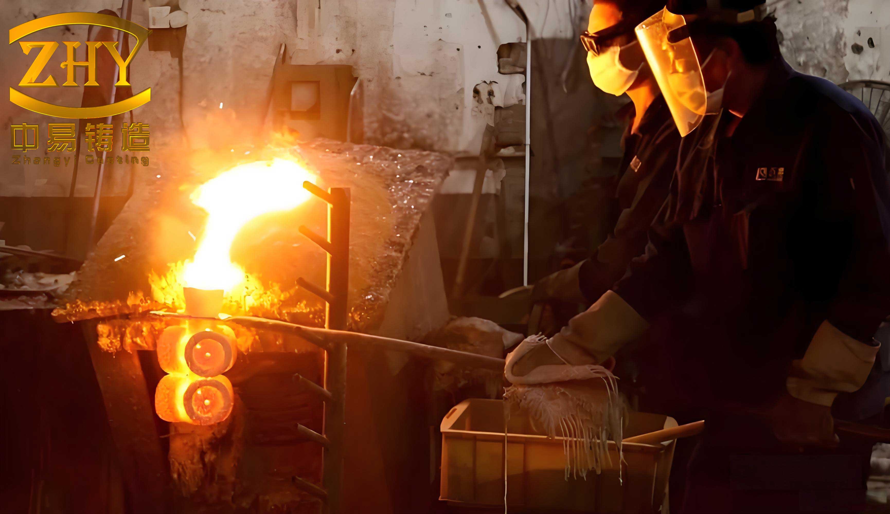
An integrated aluminum rear floor replaces a welded assembly of pressings with one casting that carries seat, suspension, luggage, and chassis loads. For a part roughly 1.5 m across, the manufacturing problem is not simply replacing stamping with casting. The wall thickness varies from 2.8 mm to 26 mm, mounting bosses create local thermal centers, and the feeding distance from a central gate to the far rail nodes can exceed the useful pressure head of the melt. Low-pressure investment casting addresses these constraints by combining a ceramic shell, which reproduces fine ribs and integral bosses, with bottom-up filling under a controlled pressure–time schedule.
Geometry, material, and casting constraints
The rear floor measures 1564 × 1456 × 619 mm and weighs 34.45 kg. It is symmetric about the vehicle centerline and consists of front, middle, and rear crossmembers, two longitudinal rails, and two intermediate longitudinal reinforcements. The nominal wall is 3 mm; the thinnest flanged sections are 2.8 mm, while the rail-to-body joints reach 6 mm. Small, deep seat and suspension mounting holes are not cast. They are left as machining stock because ceramic shell coverage and sanding inside such holes are unreliable. As a result, the boss regions reach about 20 mm in average thickness and 26 mm locally. The rib nodes on the longitudinal rails are 13 mm in diameter and up to 80 mm high. These transitions, rather than the nominal 3 mm wall, control solidification and feeding.
The selected alloy is ZL114A, an Al–Si–Mg casting alloy with nominal composition Si 6.5–7.5%, Mg 0.45–0.75%, Ti 0.08–0.25%, Fe ≤0.20%, and Al balance. Its density is 2700 kg/m3, elastic modulus 69 GPa, and Poisson ratio 0.36. The alloy combines castability with useful fatigue resistance and pressure tightness, which matters for a body panel that also acts as a load path. Its freezing range, however, is wide enough that feeding must be maintained through a dendritic network until the last liquid pocket solidifies.
Structural checks: stiffness, strength, and modal separation
Before casting design, the rear floor was checked as a load-bearing body panel. A triangular shell model with a 2 mm element size was generated in HyperMesh and solved in ANSYS. The bending case represented full load with a dynamic factor of 2.0: 350 kg for passengers and seats, 300 kg for luggage and the spare wheel, 100 kg for the rear subframe, and 50 kg for the fuel system. Left body mounts were fixed in translation, and the right mounts were constrained vertically. The torsion case represented a single rear wheel lifted, with a dynamic factor of 1.0.
| Load case | Dynamic factor | Maximum displacement | Maximum equivalent stress | Location of maximum displacement |
|---|---|---|---|---|
| Bending | 2.0 | 2.23 mm | 82 MPa | Right side of front crossmember and adjacent longitudinal reinforcement |
| Torsion | 1.0 | 3.60 mm | 111.8 MPa | Center of rear crossmember |
The model gives a bending stiffness of 2,979.73 N/mm. With a yield strength of 270–300 MPa for ZL114A, the minimum static margin is about 2.4 at the torsional peak. The displacement pattern follows the unsupported center of the front crossmember under seat and subframe mass, and the rear crossmember under luggage mass. Both are consistent with the load introduction points, and neither exceeds the stiffness or strength limit for the body structure.
Free modal analysis gave six rigid-body modes below 1 Hz. The first elastic mode is at 24.485 Hz and involves edge motion. Higher modes are concentrated in the front and rear crossmembers, which also carry the largest added masses.
| Mode | Frequency (Hz) | Dominant motion |
|---|---|---|
| 7 | 24.485 | Rear-floor edge |
| 8 | 63.891 | Front crossmember center |
| 9 | 87.769 | Rear crossmember sides |
| 10 | 91.332 | Rear crossmember center |
| 11 | 95.652 | Rear crossmember center |
| 12 | 131.84 | Front crossmember sides |
| 13 | 146.45 | Rear crossmember center |
| 14 | 163.39 | Rear-floor edge |
| 15 | 178.79 | Rear crossmember sides and edge |
| 16 | 189.25 | Rear crossmember center |
Road excitation is typically in the 1–3 Hz range, well below the first elastic mode. At rated power, the engine order is also separated from the 24.5 Hz edge mode. The modal result therefore does not indicate a primary resonance condition, although the crossmember-dominated modes show where local stiffness should be preserved in the casting.
Wax pattern injection and shell construction
The wax pattern defines the final cavity, so its filling and shrinkage behavior propagate directly into the casting. The pattern material is F28-448 filled wax, with a melt range of 61–66 °C and a recommended mold temperature of 25–35 °C. The selected injection temperature is 60 °C, the mold temperature 23 °C, and the packing time 32 s. A dual-domain mesh was used in Moldflow because the floor is thin-walled but contains thick bosses and rib transitions.
A gate-location search placed the preferred gate on the middle crossmember. Two symmetric point gates, 8 mm in diameter and 8 mm high, were selected. The sprue tapers from 16 mm to 18 mm over an 80 mm length; the trapezoidal runner is 20 mm at the top, 16 mm at the bottom, and 14 mm high. Cooling channels of 8–16 mm diameter are appropriate for the 2–4 mm wall sections.
| Parameter | Value |
|---|---|
| Pattern material | F28-448 filled wax |
| Melt range | 61–66 °C |
| Mold temperature range | 25–35 °C |
| Injection / mold temperature | 60 °C / 23 °C |
| Packing time | 32 s |
| Gate layout | Two 8 mm point gates on middle crossmember |
| Predicted fill time | 7.14 s |
| Maximum clamp force | About 900 t |
| Warpage from uneven cooling | 0.55 mm |
| Warpage from uneven shrinkage | 9.592 mm |
Filling is complete in 7.14 s, with the last material reaching the front and rear crossmembers. No short shot is predicted, but the right longitudinal rail fills more slowly than the left side. A weld line forms at the center where the two gate flows meet, and additional weld lines follow some rib paths. The maximum clamp force is about 900 t. The cooling circuit shows a large inlet-to-outlet temperature difference, which is expected in a mold of this footprint when the channels are not zoned. The shrinkage-driven warpage of 9.592 mm dominates the 0.55 mm cooling-driven component; the wax material has no orientation component. For dimensional control, gate balance and cooling zoning are therefore more important than reducing fill time alone.
After pattern assembly, the shell is built by repeated slurry dipping and stuccoing. The production route uses four and a half ceramic layers, giving a shell about 6 mm thick. The wax is removed by steam, and the shell is fired and preheated to 400–550 °C. A preheat of 550 °C reduces the melt-to-shell temperature difference and limits thermal shock during pouring, while the shell must still retain enough permeability for air evacuation.
Low-pressure filling and feeding design
In low-pressure casting, dry compressed air pressurizes a sealed crucible and pushes the melt up a riser tube into the shell. The pressure is held during solidification so that the gating system continues to feed shrinkage, and is then released so that the residual melt in the riser returns to the crucible. The hydrostatic requirement is estimated from the pressure head and a loss factor:
$$P=\mu\rho gH$$
The selected schedule uses 16.41 kPa for the 620 mm riser lift, 55.75 kPa for filling to the 1620 mm cavity top, and 111.49 kPa for holding. The nominal stages are summarized below.
| Stage | Time (s) | Pressure (kPa) |
|---|---|---|
| Riser lift | 6 | 16.41 |
| Mold filling | 14 | 55.75 |
| Pressurization | 5 | 111.49 |
| Hold | 500 | 111.49 |
| Release | 5 | 0 |
The part is oriented with its long axis vertical, and the melt enters from the bottom through a 40 mm diameter sprue. The gating is sized to keep the ingate velocity near 120 mm/s, which is low enough to avoid jetting in the cavity. The alloy is poured at 720 °C, about 107 K above its 613 °C liquidus; the solidus is 548 °C, so the freezing range is 65 K. The shell is preheated to 550 °C, the riser tube is held at 600 °C, the casting–shell interfacial heat-transfer coefficient is 500 W/(m2·K), the outer shell is air-cooled, and the critical solid fraction for feeding cutoff is 0.7.
Gating layouts and solidification response
Two bottom-gated layouts were compared. Scheme A places twelve ingates at the crossmember rib nodes, with six runners of 20 × 18 mm section. The intent is to feed the thick crossmember bosses through multiple short paths. Scheme B places four larger ingates at the longitudinal-rail rib nodes, fed by two runners of 60 × 40 mm section. The intent is to feed the rail hot spots directly, where the last liquid is expected to remain.
| Scheme | Ingate location | Runner section | Ingates | Simulated fill time | Shrinkage volume, half model |
|---|---|---|---|---|---|
| A | Crossmember rib nodes | 6 × 20 × 18 mm | 12 × 246.13 mm2 | About 20 s | 55.53 cm3 |
| B | Longitudinal-rail rib nodes | 2 × 60 × 40 mm | 4 × 1772.12 mm2 | About 36 s | 22.54 cm3 |
| B + local cooling | Longitudinal-rail rib nodes | 2 × 60 × 40 mm | 4 × 1772.12 mm2 | About 36 s | 4.61 cm3 |
Scheme A fills in about 20 s. At 0.74 s only the lowest runner is active; the full gating system engages at about 7.56 s, and the fill front is visibly uneven. That condition favors turbulence and oxide entrainment. At about 370 s the longitudinal rails remain above 600 °C while much of the thin crossmember has already solidified. The rail nodes become hydraulically isolated from the gates, and the predicted shrinkage volume reaches 55.53 cm3 in the half model. The twelve ingates feed the crossmember bosses, but they do not maintain a liquid path to the last-solidifying rail sections.
Scheme B fills in about 36 s. Metal enters the cavity at about 6 s, rises through the rails from about 19 s, and reaches the top at about 36 s. The fill front is smoother, with no pronounced jetting. At about 500 s the ingates fall below the liquidus while parts of the rail nodes remain liquid. The predicted shrinkage volume is 22.54 cm3, less than half that of Scheme A but still concentrated at the rib nodes. The result confirms that total gate area is not the controlling variable; the gate must maintain a feed path to the region that solidifies last.
Local liquid-nitrogen cooling
The residual defects in Scheme B sit at the rail rib nodes, so a local chill was applied there instead of adding more gate area. Liquid nitrogen was selected because its evaporation absorbs latent heat and its cold gas provides additional sensible cooling without water-side oxidation or contamination at the shell. Taking a latent heat of 199 kJ/kg and a gas specific heat of 1.04 kJ/(kg·K), with the gas leaving at about −60 °C after entering as liquid at −196 °C, the estimated heat sink is:
$$Q=L+c\Delta T=199+1.04(196-60)\approx340.7\ \text{kJ kg}^{-1}$$
Local delivery to the shell exterior at the rib nodes accelerates solidification at those thermal centers and shifts the last liquid toward the still-open ingates. In the symmetric half model, the shrinkage volume falls from 22.54 to 4.61 cm3, corresponding to about 9.22 cm3 for the full part. The remaining defects lie near the crossmember and rail edges, away from the main load paths, and the cooled case shows no cold shut or crack indicators in the simulation.
The cooling intensity must be controlled. A large local thermal gradient can shock the ceramic shell, and excessive nitrogen flow may cool the gate before the hot spot has been fed. The practical window is set by shell strength, nozzle placement, and the hold stage of the pressure curve, not by the cooling capacity of liquid nitrogen alone.
Manufacturing implications
The comparison shows that feeding strategy dominates defect formation in this part. Scheme A used more ingates but fed the wrong thermal centers; the longitudinal rails remained isolated and produced more than twice the shrinkage volume of Scheme B. Scheme B placed fewer but larger ingates at the rail nodes, and local liquid-nitrogen cooling reduced the predicted shrinkage by another factor of about five. For a long-freezing-range Al–Si–Mg alloy, the useful criterion is a continuous liquid path from the sprue to the last solidifying node, not simply a large total ingate area.
The wax pattern introduces a separate dimensional risk. Shrinkage-driven warpage of 9.592 mm is much larger than the 0.55 mm cooling-driven component, so the tool cooling layout and gate balance need to be zoned across the 1.5 m footprint. The 900 t clamp force is a tooling constraint, and the inlet-to-outlet temperature spread in the cooling circuit indicates that a single uniform channel layout is unlikely to hold the pattern within tolerance.
The structural model supports the integrated approach: the rear floor carries the full-load bending and torsion cases with a minimum static margin of about 2.4, and the first elastic mode at 24.485 Hz is separated from road and rated-power engine excitation. The crossmember-dominated modes also identify where local stiffness should be retained rather than removed for weight saving.
The principal process penalty is cycle time. A four-and-a-half-layer shell and a 500 s hold are slow compared with high-pressure die casting, but the low-pressure investment route provides a quiescent fill and a sustained feed path that are difficult to achieve in a large, thin-walled aluminum body casting. The predicted defect volumes are comparative simulation results, not measured porosity. Production qualification would require instrumented pours to calibrate the interfacial heat transfer and shell permeability, CT or sectioning at the rail nodes, dimensional inspection across the full footprint, and tensile testing of coupons cut from the casting.