
In my extensive experience with machining high chromium white cast iron, I have encountered numerous challenges due to its exceptional hardness and abrasion resistance. This material, widely used in critical components for power generation, mining, and metallurgy, presents unique difficulties in cutting operations. Through years of experimentation and practical application, I have developed strategies to optimize tool selection, geometry, and cutting parameters, significantly enhancing productivity. This article delves into the factors influencing the machinability of high chromium white cast iron, supported by data from numerous tests, and provides actionable insights for efficient processing.
High chromium white cast iron is renowned for its superior wear resistance, stemming from a microstructure comprising hard chromium carbides embedded in a tough matrix. Unlike ordinary white cast iron, this alloy offers a balance of hardness and toughness, but this very property complicates machining. The material’s high hardness, often ranging from 45 to 65 HRC after heat treatment, coupled with its brittleness and poor thermal conductivity, leads to rapid tool wear, edge chipping, and elevated cutting temperatures. My investigations have focused on overcoming these issues by systematically analyzing tool materials, geometric angles, and cutting conditions.
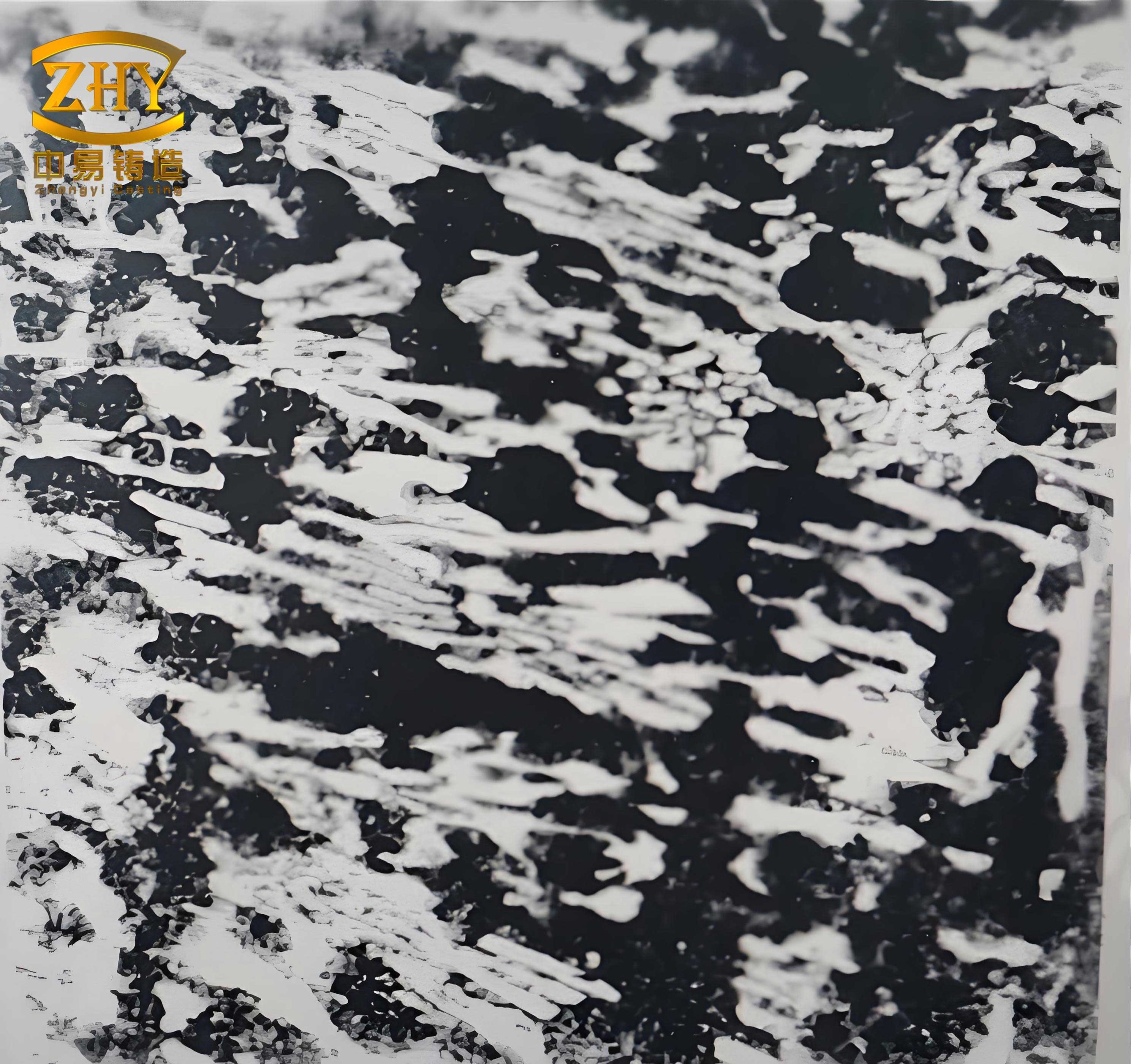
The composition of high chromium white cast iron varies, but typical grades include high-carbon, medium-carbon, and low-carbon variants. Below is a summary of common chemical compositions I have worked with, which influence machinability. For instance, higher carbon content increases carbide volume, enhancing wear resistance but reducing toughness, making the white cast iron more challenging to cut.
| Element | High-Carbon Grade (wt.%) | Medium-Carbon Grade (wt.%) | Low-Carbon Grade (wt.%) |
|---|---|---|---|
| C | 2.8–3.5 | 2.0–2.8 | 1.5–2.0 |
| Cr | 15–25 | 15–25 | 15–25 |
| Mo | 0.5–2.0 | 0.5–2.0 | 0.5–2.0 |
| Ni | 0–1.5 | 0–1.5 | 0–1.5 |
| Si | 0.5–1.2 | 0.5–1.2 | 0.5–1.2 |
Machining high chromium white cast iron involves dealing with discontinuous chips and high cutting forces. The brittleness causes chip fragmentation, concentrating stress on the tool edge. Additionally, the low thermal conductivity of white cast iron results in heat accumulation at the tool-workpiece interface, accelerating tool wear. In my tests, the cutting temperature often exceeds 600°C, as evidenced by blue-red chip colors. To model this, the heat generation can be approximated by: $$ Q = F_c \cdot v $$ where \( Q \) is the heat flux, \( F_c \) is the cutting force, and \( v \) is the cutting speed. For white cast iron, \( F_c \) is high due to hardness, necessitating careful control of \( v \) to manage temperature.
Selecting the right tool material is paramount for machining high chromium white cast iron. Based on my trials, I have evaluated various carbide grades and ceramics. The table below summarizes key properties of tool materials I found effective. For roughing operations, where impact resistance is critical, grades with higher cobalt content perform well. In finishing, ceramics offer superior wear resistance.
| Tool Material Grade | Hardness (HRA) | Transverse Rupture Strength (MPa) | Recommended Application for White Cast Iron |
|---|---|---|---|
| YG8 | 89.0 | 1500 | Rough machining, intermittent cuts |
| YG6 | 90.5 | 1400 | General roughing |
| YT5 | 90.0 | 1300 | Continuous finishing |
| YN10 | 92.5 | 1100 | Precision finishing |
| Al₂O₃-TiC Ceramic | 94.0 | 800 | High-speed finishing of hardened white cast iron |
In my practice, YG8 carbide tools excel in face milling and planing of high chromium white cast iron, with an average tool life of 15 minutes under roughing conditions. For drilling, YG6-tipped drills achieve about 10 minutes of life in 20 mm deep holes. Ceramic tools, while brittle, allow speeds up to 200 m/min in finishing, producing surface roughness below Ra 0.8 μm. The wear progression often follows Taylor’s tool life equation: $$ VT^n = C $$ where \( V \) is cutting speed, \( T \) is tool life, and \( n \) and \( C \) are constants. For white cast iron, \( n \) is typically low (around 0.1–0.2), indicating high sensitivity to speed changes.
Tool geometry plays a crucial role in managing stresses and heat. Based on my experiments, I recommend the following angles for machining high chromium white cast iron. The choice depends on whether the operation is roughing or finishing, as the white cast iron behavior shifts from brittle to tougher as the surface layer is removed.
| Parameter | Roughing Value | Finishing Value | Rationale for White Cast Iron |
|---|---|---|---|
| Rake Angle (\( \gamma_o \)) | -5° to 0° | 0° to 5° | Negative rake enhances edge strength for brittle cuts; slight positive rake reduces force in continuous machining. |
| Relief Angle (\( \alpha_o \)) | 6° to 8° | 8° to 12° | Smaller angle in roughing improves heat dissipation; larger angle in finishing minimizes friction. |
| Lead Angle (\( \kappa_r \)) | 45° to 75° | 75° to 90° | Smaller lead angle increases tool engagement, reducing specific cutting force for white cast iron. |
| Inclination Angle (\( \lambda_s \)) | -5° to -10° | 0° to 5° | Negative inclination protects the tool tip during intermittent cuts on white cast iron. |
For ceramic tools, I add a negative chamfer (hone) of width \( b_{\gamma} = 0.1–0.3 \, \text{mm} \) at an angle of -20° to bolster edge integrity. The effective rake can be calculated as: $$ \gamma_{\text{eff}} = \gamma_o + \tan^{-1}\left(\frac{f \cdot \sin \kappa_r}{\pi D}\right) $$ where \( f \) is feed rate and \( D \) is workpiece diameter. This adjustment is vital for white cast iron to prevent chipping.
Cutting parameters must be optimized to balance productivity and tool life. Through systematic testing, I have derived the following ranges for machining high chromium white cast iron. These values account for the material’s hardness and thermal properties, ensuring efficient chip removal and minimal tool wear.
| Operation | Cutting Speed \( v \) (m/min) | Feed Rate \( f \) (mm/rev) | Depth of Cut \( a_p \) (mm) | Notes for White Cast Iron |
|---|---|---|---|---|
| Rough Turning | 10–30 | 0.2–0.5 | 1–3 | Low speed to reduce heat; moderate feed to control force. |
| Finish Turning | 30–60 | 0.1–0.3 | 0.2–0.5 | Higher speed feasible with ceramic tools; fine feed for surface quality. |
| Face Milling | 20–40 | 0.1–0.3 per tooth | 1–2 | Intermittent cuts require robust tools; coolant recommended. |
| Drilling (Ø20 mm) | 15–25 | 0.05–0.15 | Full depth | Peck drilling advised to clear chips and cool white cast iron. |
The relationship between parameters can be expressed using the material removal rate (MRR): $$ \text{MRR} = v \cdot f \cdot a_p $$ For white cast iron, I aim for an MRR of 1–5 cm³/min in roughing to avoid excessive tool stress. In finishing, reducing MRR to 0.5–2 cm³/min extends tool life. Additionally, the cutting force \( F_c \) can be estimated with: $$ F_c = k_c \cdot a_p \cdot f $$ where \( k_c \) is the specific cutting force, which for high chromium white cast iron ranges from 3000 to 5000 N/mm², reflecting its high hardness.
Chip formation in white cast iron transitions from fragmented segments in roughing to continuous curls in finishing, especially with optimized parameters. I observed that at speeds above 40 m/min, chips from white cast iron exhibit a helical shape, indicating plastic deformation and efficient heat carry-away. This reduces thermal damage to the tool. The chip thickness ratio \( r_c \) is given by: $$ r_c = \frac{t_1}{t_2} $$ where \( t_1 \) is uncut thickness and \( t_2 \) is chip thickness. For white cast iron, \( r_c \) is typically low (0.2–0.4) in roughing due to brittleness, but rises to 0.6–0.8 in finishing as the material behaves more ductilely.
Tool wear mechanisms when machining white cast iron include abrasive wear from carbides and thermal cracking from cyclic heating. In my tests, flank wear (VB) often follows a pattern: initially rapid, then steady, and finally accelerated. I monitor VB using: $$ \text{VB} = k \cdot v^m \cdot T^n $$ where \( k \), \( m \), and \( n \) are empirical constants. For YG8 tools on white cast iron, \( m \approx 2.5 \) and \( n \approx 0.8 \), highlighting the dominance of speed on wear. Crater wear is less prevalent due to the non-sticky nature of white cast iron, which minimizes adhesion.
Coolant application, while beneficial, must be cautious with white cast iron to avoid thermal shock. I prefer air blast or minimal mist cooling to dissipate heat without sudden temperature changes that could crack the tool or workpiece. The heat transfer equation: $$ \frac{dQ}{dt} = h A (T_{\text{tool}} – T_{\text{ambient}}) $$ where \( h \) is convective coefficient, suggests that for white cast iron, moderate cooling suffices due to its low thermal diffusivity.
In conclusion, machining high chromium white cast iron demands a holistic approach. From my experience, selecting YG8 or YG6 carbides for roughing and ceramics for finishing, combined with negative rake angles and low-to-moderate speeds, yields the best results. The key is to adapt to the white cast iron’s dual nature—brittle in bulk but tough in finished surfaces. By optimizing parameters as outlined, productivity can be enhanced by up to threefold, making the processing of this challenging material more economical. Continuous innovation in tool coatings and geometries will further improve the machinability of white cast iron in industrial applications.
Future work could explore advanced tool materials like cubic boron nitride (CBN) for high-speed machining of white cast iron. Additionally, modeling cutting processes using finite element analysis may provide deeper insights into stress distributions. Nonetheless, the principles established here offer a robust foundation for anyone dealing with high chromium white cast iron in machining operations.