
Valve body castings operating in high-temperature and high-pressure environments, such as those in petrochemical systems (14–25 MPa, ~400°C), demand exceptional strength, wear resistance, and corrosion immunity. Defects like inclusions, porosity, shrinkage, or cracks are unacceptable. This article details the casting and metallurgical processes for CF8C stainless steel valve body castings, validated through rigorous quality testing.
Technical Requirements
CF8C valve body castings must comply with ASTM A351 specifications for chemistry and mechanical properties. Key parameters include:
| Element | C | Si | Mn | S | P | Cr | Ni | Mo | Nb |
|---|---|---|---|---|---|---|---|---|---|
| wt.% | ≤0.08 | ≤2.00 | ≤1.50 | ≤0.015 | ≤0.020 | 18.0–21.0 | 9.0–12.0 | ≤0.50 | 8×C–1.00 |
| Property | Rm (MPa) | ReL (MPa) | ALo (%) |
|---|---|---|---|
| Requirement | ≥485 | ≥205 | ≥30 |
Additional specifications:
- Microstructure: Ferrite content: 4–16% (ASTM E381).
- Inclusions: Max ratings: Sulfides (A) ≤1.0, Silicates (B) ≤1.5, Aluminates (C) ≤1.0, Globular Oxides (D) ≤2.0; Total ≤5.0 (ASTM E45).
- Intergranular Corrosion: Pass ASTM A262 Practice E (Copper–Copper Sulfate–Sulfuric Acid).
- Non-Destructive Testing: 100% RT (ASME B16.34, MSS SP-54), 100% PT (ASTM E165).
Casting Process Design for Valve Body Casting
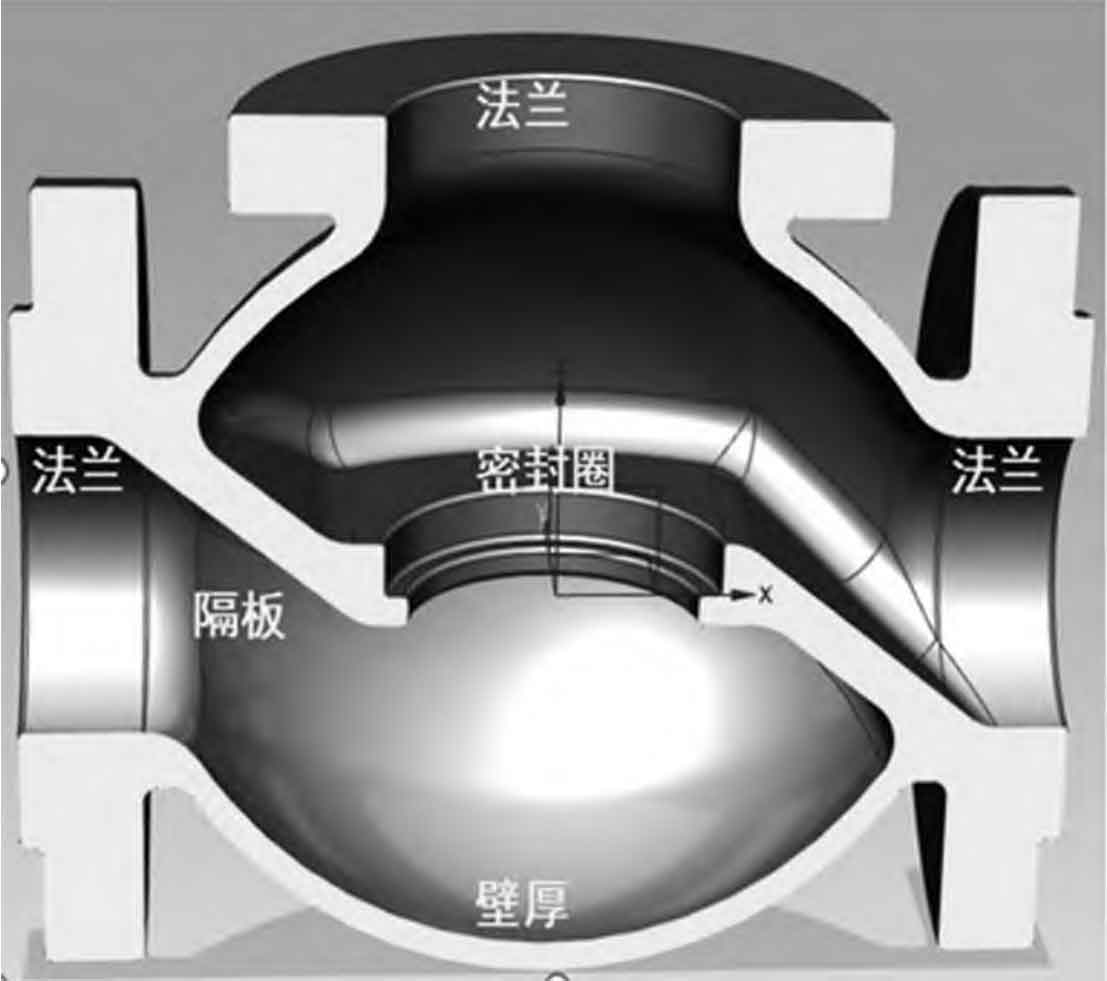
The DN400-2500lb valve body casting (4,300 kg, dimensions: 1,538 × 1,310 × 840 mm) exemplifies a complex triple-tube geometry with uniform wall thickness (115 mm) and intersecting thermal sections. Key design considerations include:
Process Parameters
- Shrinkage Allowance: 2.0% (external), 1.5% (internal) due to constrained contraction of CF8C austenitic stainless steel.
- Parting Line: Defined along the plane of the three pipe centers (Figure 2 schematic). This minimizes cores, reduces misalignment, eliminates flash, and ensures dimensional accuracy.
Gating and Risering System
A bottom-gating system ensures calm filling, minimizes oxidation/slag entrainment, and facilitates gas venting. Critical calculations:
Pouring Time (t): Determined by casting mass (G = 9,350 kg):
$$ t = 105 \text{s} $$
Metal Rise Velocity (v): Critical for avoiding cold shuts (target: 10–20 mm/s):
$$ v = \frac{H}{t} = \frac{1560}{105} \approx 15 \text{mm/s} $$
where \( H \) is casting height (mm).
Mass Flow Rate (V): For one ladle with one nozzle:
$$ V = \frac{G}{t} = \frac{9350}{105} \approx 89 \text{kg/s} $$
A \( \varnothing 60 \text{mm} \) nozzle achieves this flow. The open gating ratio is designed as:
$$ F_{\text{nozzle}} : F_{\text{sprue}} : F_{\text{runner}} : F_{\text{ingate}} = 1 : 1.8 : 1.8 : 2.4 $$
Yielding: Sprue = \( \varnothing 80 \text{mm} \), Runner = \( \varnothing 80 \text{mm} \), 4 Ingates = \( \varnothing 50 \text{mm} \).
Risering: Riser necks connect risers to pipe intersections and ports, enhancing directional solidification. Indirect chills (30–50 mm chromite sand backing) accelerate cooling at thermal nodes.
Molding Materials
- Furan no-bake silica sand for molds/cores.
- Double-layer coating: Zircon-based wash + Magnesia-based wash to prevent burn-on.
Melting Process: Electric Arc Furnace (EAF) Return Oxygen Blowing
Producing low-sulfur/low-phosphorus CF8C requires stringent control:
| Stage | Parameters | Control Objectives |
|---|---|---|
| Charging | 90% CF8C returns, 1.0–1.5% FeSi, Ni @ 9.5–10.5% | Basicity control, Ni alloying |
| Melting | Tap ≥1,600°C, partial slag removal | Prepare for decarburization |
| Oxidation | 1,705–1,835°C, dual-tube O2 blowing @ 1.5–1.8 MPa, 18–22 min | Decarburize to C ≤ 0.03% |
| Reduction | White slag, FeCr addition, power: 180–210 V, 8–10 kA | Cr recovery, deoxidation |
To counter poor fluidity from Cr-oxide films, argon-shielded pouring at elevated temperatures is essential.
Quality Validation of Valve Body Casting
Produced valve body castings met all specifications:
| Heat No. | C | Si | Mn | S | P | Cr | Ni | Nb |
|---|---|---|---|---|---|---|---|---|
| C13-206 | 0.06 | 0.71 | 0.71 | 0.007 | 0.020 | 18.30 | 9.52 | 0.049 |
| C13-210 | 0.07 | 0.74 | 0.67 | 0.005 | 0.020 | 18.91 | 9.33 | 0.059 |
| Sample ID | ReL (MPa) | Rm (MPa) | ALo (%) | Z (%) |
|---|---|---|---|---|
| 3C688 | 290 | 530 | 46.5 | 66.0 |
| 3C748 | 275 | 515 | 53.5 | 59.5 |
Additional results:
- Microstructure: Austenite + 4.5–5.5% ferrite (ASTM E381), inclusion ratings within limits.
- Corrosion: Passed ASTM A262 Practice E.
- NDT: RT: Shrinkage ≤ Grade 2 (MSS SP-54). PT: No linear defects >2 mm, no rounded defects >4 mm.
Conclusions
Optimized casting parameters—parting line selection, directional solidification via riser/neck/chill design, and rapid bottom-pouring—effectively eliminate defects in complex valve body castings. The EAF return oxygen blowing process, utilizing high silicon/nickel levels, dual-tube high-pressure oxygen injection, and controlled power input during reduction, achieves stringent low-sulfur/low-phosphorus CF8C chemistry. This integrated approach ensures valve body castings meet extreme service demands in high-temperature, high-pressure, and corrosive environments.