
In my decades of experience in the heavy casting industry, particularly focusing on large-scale housing castings for rolling mills, I have encountered and addressed a wide array of defects that can compromise the integrity and performance of these critical components. Common issues include cracks, sand drop, slag inclusion, shrinkage porosity, and coarse grain structure. Each defect presents unique challenges, and through systematic analysis and practical application, I have developed robust strategies for prevention and remediation. This article distills my firsthand knowledge into a comprehensive guide, emphasizing the importance of process control, metallurgical quality, and design optimization. I will delve deeply into each defect category, incorporating technical formulas, data tables, and actionable insights to empower foundry professionals in minimizing losses and enhancing product reliability.
One of the most pervasive and troublesome defects I have dealt with is cracking. Cracks typically manifest in high-stress regions such as beneath risers, at sharp corners of large protrusions, around window openings, and near pressure screw holes. The root cause often lies in internal stresses exceeding the material strength, exacerbated by inadequate feeding, design flaws, or processing errors. For instance, the substantial solidification shrinkage in massive castings requires efficient feeding from large risers. However, these risers solidify slowly, leading to coarse grains and chemical segregation, which weaken the underlying material. To quantify the risk, I frequently use thermal stress analysis based on the temperature gradient \(\Delta T\) and the coefficient of thermal expansion \(\alpha\). The stress \(\sigma\) can be approximated as:
$$ \sigma = E \cdot \alpha \cdot \Delta T $$
where \(E\) is Young’s modulus. When \(\sigma\) surpasses the yield strength \(\sigma_y\) at elevated temperatures, hot tearing occurs. Therefore, controlling cooling rates is paramount. I often apply Chvorinov’s rule to estimate solidification time \(t_s\) for different sections:
$$ t_s = k \left( \frac{V}{A} \right)^2 $$
where \(k\) is a mold constant, \(V\) is volume, and \(A\) is cooling surface area. By ensuring that riser sections have a higher modulus \(M = V/A\) than the casting, directional solidification can be promoted. Moreover, I advocate for the use of chills to accelerate cooling in isolated hot spots. The chill effectiveness can be modeled using the heat transfer coefficient \(h\) and the Biot number \(Bi\):
$$ Bi = \frac{h L_c}{k_m} $$
where \(L_c\) is characteristic length and \(k_m\) is thermal conductivity of the metal. A \(Bi > 0.1\) indicates significant external resistance, justifying chill placement. To summarize crack prevention, I have compiled a table of targeted measures based on defect location:
| Defect Location | Primary Causes | Preventive Actions | Technical Parameters |
|---|---|---|---|
| Beneath risers | Poor feeding, segregation, coarse grains | Optimize riser design using modulus method; use exothermic or insulating sleeves; control steel chemistry (C low, Ti addition) | Riser modulus \(M_r > 1.2 M_c\); feeding distance \(L = 5\sqrt{t}\) cm; solidification time ratio \(t_s(\text{riser})/t_s(\text{casting}) > 1.5\) |
| Sharp corners and protrusions | Stress concentration, early solidification | Increase fillet radii (\(R \geq 50\) mm); place anti-cracking ribs; use padding to balance cooling | Stress concentration factor \(K_t = 1 + 2\sqrt{a/r}\) where \(a\) is depth, \(r\) is radius; aim for \(K_t < 2\) |
| Window openings | Restrained contraction, sand adhesion | Enlarge fillets; incorporate cushion layers (e.g., coke breeze) in cores; avoid hard ramming; consider yieldable core designs | Contraction allowance \(\varepsilon = \alpha \Delta T \approx 2\%\) for steel; core cushion thickness \(\delta \approx 20-30\) mm |
| Pressure screw holes | Core deformation, sand burning, cleaning stress | Reinforce cores with steel plates and welded rebar; add loose layers; cast solid if possible; use high-refractoriness coatings | Core compressive strength \(\sigma_c > 0.5\) MPa at 1000°C; thermal expansion mismatch \(\Delta \alpha < 5 \times 10^{-6}\)/°C |
Another critical category involves sand-related defects and, notably, slag inclusion defects. These defects are particularly insidious as they act as stress concentrators and can lead to premature failure under cyclic loading. In my practice, slag inclusion defects often originate from non-metallic inclusions in the molten steel or from mold erosion during pouring. To address steel cleanliness, I emphasize rigorous ladle refining. The effectiveness of deoxidation can be assessed via the oxygen activity \(a_O\), which should be maintained below 30 ppm for high-integrity castings. The use of calcium treatment modifies inclusions to a globular morphology, reducing their harmful effects. The inclusion removal rate can be described by Stokes’ law:
$$ v = \frac{2 g r^2 (\rho_m – \rho_i)}{9 \eta} $$
where \(v\) is rise velocity, \(g\) is gravity, \(r\) is inclusion radius, \(\rho_m\) and \(\rho_i\) are densities of metal and inclusion, and \(\eta\) is viscosity. Increasing \(v\) through argon stirring or filtration enhances inclusion flotation. Additionally, gating system design is crucial to minimize turbulence, which can entrain slag. I often employ Bernoulli’s principle to calculate flow velocities:
$$ v = \sqrt{2 g h} $$
where \(h\) is the metallostatic head. Keeping \(v\) below 0.5 m/s in the mold cavity reduces slag entrainment. The Reynolds number \(Re\) helps assess flow regime:
$$ Re = \frac{\rho v D}{\mu} $$
where \(D\) is hydraulic diameter and \(\mu\) is dynamic viscosity. Laminar flow (\(Re < 2000\)) is ideal to avoid slag inclusion defects. Furthermore, mold material quality is paramount. I insist on using high-purity silica sand with controlled clay content and adequate binder levels. Regular testing of sand properties, such as green strength and permeability, is essential. Permeability \(P\) is measured as:
$$ P = \frac{V \cdot h}{A \cdot t \cdot \Delta P} $$
with typical values of 100-150 for large steel castings. Low permeability can lead to gas defects, while high permeability may cause erosion. To encapsulate best practices, I have developed a table focusing on slag inclusion defect prevention:
| Aspect | Key Measures | Technical Specifications | Expected Outcome |
|---|---|---|---|
| Steelmaking | Deoxidation with Al (0.02-0.06%); calcium treatment; slag control; ladle refining | Oxygen activity \(a_O < 30\) ppm; inclusion density \(< 10\) inclusions/cm²; sulfur content \(< 0.010\%\) | Reduced non-metallic inclusions; improved toughness |
| Gating Design | Tapered sprue; slag traps; ceramic filters; bottom gating; minimize turbulence | Sprue area ratio 1:2:4; filter pore size 10-20 ppi; flow velocity \(v < 0.5\) m/s; \(Re < 2000\) | Laminar flow; effective slag capture; clean metal entry |
| Mold Materials | High-refractoriness sand; proper binder; coatings (zircon, chromite); controlled drying | Sand SiO₂ > 95%; LOI < 0.5%; coating thickness 0.2-0.5 mm; drying temperature 200-300°C | Reduced erosion; minimal sand inclusion; better surface finish |
| Pouring Practice | Simultaneous ladle opening; controlled temperature; use of tundish; slag skimming | Pouring temperature \(T_p = T_l + 20-30°C\) (where \(T_l\) is liquidus); rise speed > 10 mm/s; pour time \(t_p\) optimized via \(t_p = k \sqrt{W}\) with \(k \approx 1.5\) s/kg¹/² | Minimized exposure; reduced slag entrainment; uniform filling |
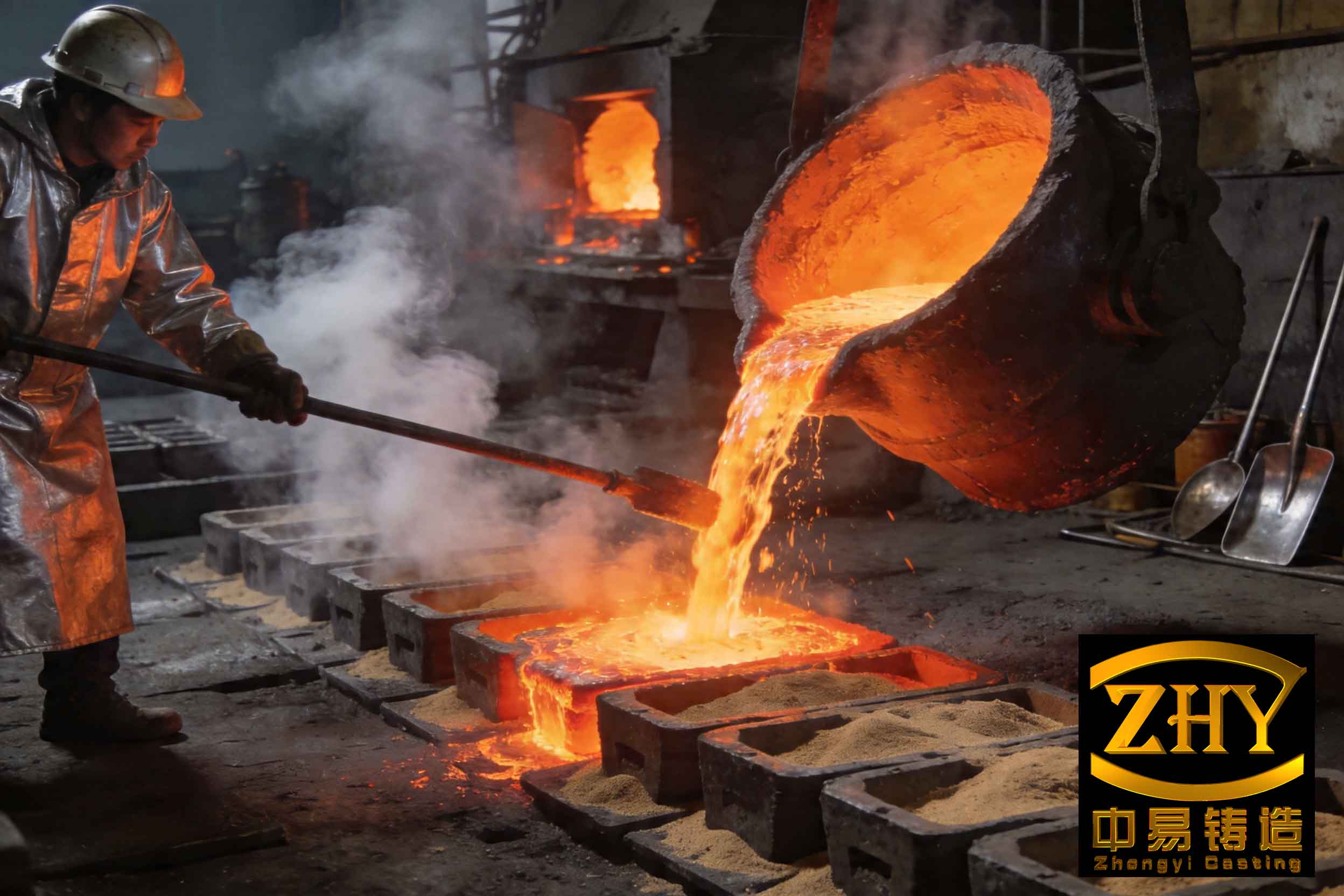
The image above illustrates typical slag inclusion defects in castings, highlighting the importance of vigilance in both process and material selection. In my experience, preventing slag inclusion defects requires a holistic approach, integrating metallurgical control, gating design, and mold quality. For instance, I have found that using ceramic filters in the gating system can reduce slag inclusion defects by over 50%, as captured by the filtration efficiency \(\eta_f\):
$$ \eta_f = 1 – \frac{C_o}{C_i} $$
where \(C_o\) and \(C_i\) are outlet and inlet inclusion concentrations. With proper design, \(\eta_f\) can exceed 0.8. Additionally, mold coatings based on chromite or zircon significantly improve surface hardness, reducing sand penetration. The penetration depth \(d_p\) can be estimated using Darcy’s law:
$$ d_p = \sqrt{\frac{2 K P t}{\mu}} $$
where \(K\) is permeability, \(P\) is metal pressure, and \(t\) is time. By reducing \(K\) through coatings, \(d_p\) is minimized, thereby lowering the risk of slag inclusion defects from mold erosion.
Shrinkage porosity and cavities are inherent challenges in heavy castings due to the large volume of molten metal and significant solidification shrinkage. In my work, I have refined techniques to ensure adequate feeding. The modulus method remains a cornerstone for riser design. For complex geometries, I often segment the casting into thermal nodes and calculate the modulus \(M = V/A\) for each. To ensure soundness, the riser modulus \(M_r\) must satisfy:
$$ M_r \geq 1.2 M_c $$
where \(M_c\) is the casting modulus. Additionally, the feeding volume required \(V_f\) can be derived from the shrinkage factor \(\beta\) (approximately 6% for steel):
$$ V_f = \beta V_c $$
where \(V_c\) is casting volume. Riser dimensions are then sized to provide this volume, considering feeding efficiency \(\eta_r\) (typically 0.1-0.3 for conventional risers). Exothermic risers can boost \(\eta_r\) to 0.4-0.6. I also employ chills to create directional solidification. The chill spacing \(S\) is critical and can be approximated as:
$$ S = 4 \sqrt{\alpha t_s} $$
where \(\alpha\) is thermal diffusivity. Furthermore, I use simulation software to predict shrinkage zones, but empirical rules still guide initial designs. For example, the feeding distance \(L\) from a riser in a plate-like section is:
$$ L = 4.5 \sqrt{t} $$
for end-fed plates, where \(t\) is thickness in cm. Beyond this, auxiliary risers or chills are needed. The table below summarizes key parameters for shrinkage control:
| Parameter | Definition | Calculation/Value | Application Note |
|---|---|---|---|
| Modulus ratio | \(R_m = M_r / M_c\) | \(R_m \geq 1.2\) for steel; higher for alloys | Ensures riser solidifies last; adjust with padding |
| Shrinkage volume | \(V_f = \beta V_c\) | \(\beta = 0.06\) for carbon steel; 0.08 for high-alloy | Size risers to contain \(V_f\); include safety factor 1.5 |
| Feeding efficiency | \(\eta_r = V_{\text{feed}} / V_r\) | 0.15 for sand risers; 0.5 for exothermic | Select riser type based on \(\eta_r\); consider cost |
| Chill capacity | \(Q_c = m c_p \Delta T\) | \(m\) is chill mass; \(c_p\) specific heat; \(\Delta T\) temperature rise | Design chills to absorb heat equivalent to local hot spot |
| Solidification gradient | \(G = \Delta T / \Delta x\) | Aim for \(G > 10\) °C/cm in feeding direction | Use chills and insulation to steepen \(G\) |
Coarse grain structure is another defect I frequently encounter in thick-section castings. The prolonged solidification time allows dendrites to grow extensively, resulting in large grains that impair mechanical properties, particularly toughness and fatigue resistance. To combat this, I focus on grain refinement through inoculation and controlled cooling. The addition of titanium (0.01-0.03%) forms TiN particles that act as heterogeneous nucleation sites. The resulting grain size \(d\) can be predicted using the Johnson-Mehl-Avrami-Kolmogorov equation:
$$ d = \left( \frac{\pi G}{3 N} \right)^{1/4} $$
where \(G\) is growth rate and \(N\) is nucleation density. By maximizing \(N\), \(d\) can be reduced significantly. Moreover, heat treatment plays a crucial role. I recommend normalizing at temperatures 30-50°C above the \(A_3\) transformation point, followed by air cooling. The cooling rate \(\dot{T}\) must be controlled to avoid excessive stress yet ensure grain refinement. The critical cooling rate for avoiding ferrite-pearlite transformation in low-alloy steels is:
$$ \dot{T}_c = \frac{T_{\text{norm}} – T_{500}}{t_{500}} $$
where \(T_{500}\) is 500°C and \(t_{500}\) is time to cool to 500°C. Typically, \(\dot{T}_c\) should exceed 20°C/min for effective grain refinement. Additionally, I use ultrasonic testing to assess grain size indirectly via attenuation coefficient \(\alpha_a\):
$$ \alpha_a = \frac{1}{x} \ln \left( \frac{A_0}{A} \right) $$
where \(x\) is distance, \(A_0\) and \(A\) are initial and received amplitudes. High \(\alpha_a\) may indicate coarse grains or scattering from inclusions. To ensure uniformity in large castings, I advocate for multi-zone furnace control with thermocouples placed strategically. The temperature uniformity \(U\) can be defined as:
$$ U = \frac{T_{\max} – T_{\min}}{T_{\text{set}}} $$
and should be kept below 0.1 during soaking. The table below outlines strategies for grain refinement:
| Technique | Mechanism | Implementation | Expected Grain Size Reduction |
|---|---|---|---|
| Inoculation | Heterogeneous nucleation via Ti, B, or rare earth additions | Add Ti wire during tapping; aim for 0.02% Ti; ensure good mixing | Grain size reduction by 30-50%; ASTM grain size 5-7 |
| Controlled solidification | Enhanced cooling using chills or mold materials | Place chills at hot spots; use zircon sand for higher cooling; optimize pouring temperature | Increased nucleation rate; dendritic arm spacing reduced |
| Heat treatment | Phase transformation and recrystallization | Normalize at 900-950°C for 1 h per 25 mm thickness; air cool; temper at 600-650°C | Full microstructure homogenization; grain size ASTM 4-6 |
| Ultrasonic vibration | Cavitation-induced nucleation during solidification | Apply ultrasonic probes to mold during pouring; frequency 20-40 kHz | Grain refinement up to 40%; experimental but promising |
When defects occur despite preventive measures, effective remediation is essential to salvage castings and avoid costly scrapping. For cracks, I always begin with non-destructive testing (NDT) to map the extent. Magnetic particle testing is excellent for surface cracks, while ultrasonic testing probes subsurface issues. Before repair, I preheat the area to 300-400°C to reduce thermal stress, using the preheat temperature \(T_p\) calculated as:
$$ T_p = 200 + 150 \log_{10}(t) $$
where \(t\) is thickness in mm. For weld repair, I select filler metals matching the base chemistry and employ low-hydrogen electrodes to avoid cracking. Post-weld heat treatment at 600-650°C for stress relief is mandatory, with soaking time \(t_s\) given by:
$$ t_s = \frac{25 \cdot t}{25} \text{ hours} $$
where \(t\) is thickness in inches (or 1 hour per 25 mm). For slag inclusion defects, if they are near the surface, grinding may suffice, but deep-seated slag inclusion defects require weld repair after complete removal. I often use arc gouging or milling, followed by dye penetrant inspection to verify cleanliness. The defect removal volume \(V_d\) should extend beyond the visible defect by a factor of 1.5 to ensure no residual stress concentrators. For shrinkage cavities, I sometimes employ impregnation with epoxy resins under vacuum for non-critical applications, but for high-integrity castings, weld repair is preferred. The weld metal deposition rate \(R_d\) can be estimated as:
$$ R_d = \frac{I V}{\eta} $$
where \(I\) is current, \(V\) is voltage, and \(\eta\) is efficiency (0.8-0.9). For coarse grains detected via ultrasonic backscatter, a secondary normalizing heat treatment can be applied, carefully controlling the cooling rate to avoid distortion. Throughout remediation, documentation and analysis are crucial to prevent recurrence. I maintain a defect log with parameters like pouring temperature, mold conditions, and repair methods, using statistical process control to identify trends.
In conclusion, mastering defect control in heavy casting is an ongoing journey that blends science with art. From cracking to slag inclusion defects, each challenge demands a deep understanding of materials, processes, and design. Through relentless attention to detail, continuous improvement, and the application of robust preventive measures, the quality and reliability of housing castings can be elevated to meet the stringent demands of modern industry. I encourage foundry professionals to embrace data-driven approaches, leverage simulation tools, and foster a culture of quality to turn defects into opportunities for innovation and excellence.