
In the demanding world of industrial machinery manufacturing, the production of complex, high-integrity components often requires specialized foundry techniques. This is particularly true for chain grate machines, critical equipment in sintering and pelletizing processes, which consist of thousands of individual, intricate cast parts. Based on my extensive experience, the lost wax investment casting process stands out as the premier method for producing these components. The inherent advantages of this investment casting technique—excellent surface finish, high dimensional accuracy, and the ability to form complex geometries—make it the optimal choice for parts like grate plates and chain links. This article details the comprehensive application of the lost wax investment casting process for a full set of chain grate machine parts, encompassing process design, parameter optimization, and solutions to common production challenges.
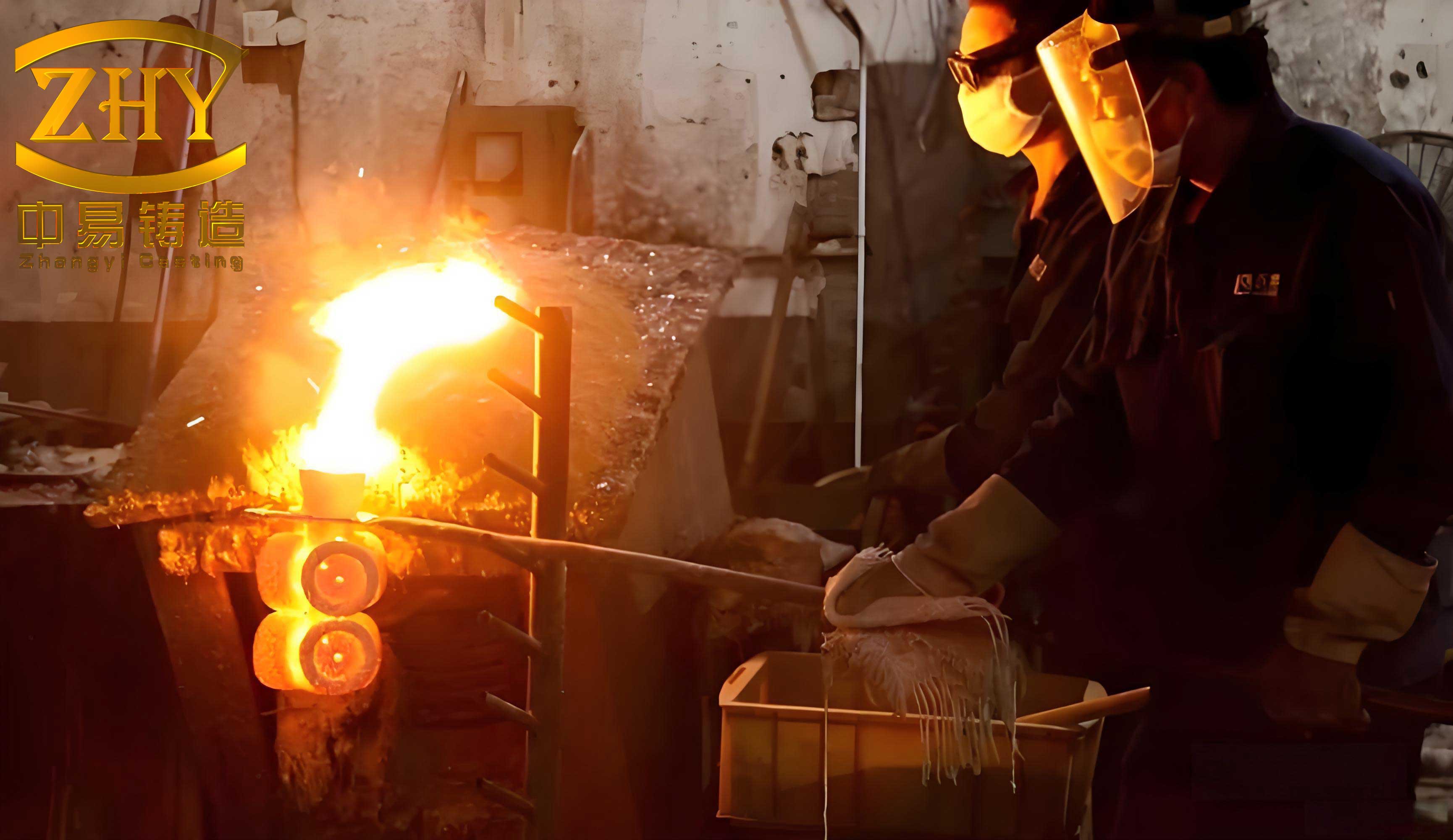
The lost wax investment casting process, also known simply as precision casting, involves creating a wax or thermoplastic pattern, coating it with successive layers of refractory ceramic material to build a robust shell, melting or dissolving the pattern out to leave a precise cavity, and then pouring molten metal into this pre-fired mold. For high-volume production of steel components like those for chain grates, wax-based pattern materials are typically employed. In this application, a medium-temperature wax with superior thermal stability was used, ensuring pattern integrity during handling and the initial coating stages. The entire success of the investment casting operation hinges on meticulous planning at every stage, from tree assembly design to final pouring.
Process Design and Gating System Configuration
The first critical step in lost wax investment casting is the design of the casting process itself. Each component type—clamping blocks, side plates, chain links, and grate plates—presents unique geometrical challenges that demand tailored gating and feeding systems to ensure soundness and dimensional accuracy.
Clamping Blocks (ZG45): These are small, simple parts ideal for high-density assembly on a casting tree. To facilitate coating and dewaxing, gates were attached to the side edges. A central down sprue feeds multiple parts arranged laterally. The cross-sectional area of the sprue must adequately feed all gates to prevent mist runs. The relationship is defined as:
$$A_{sprue} = 1.4 \times \sum A_{gate}$$
For a tree with 24 blocks, if the sprue diameter is 80 mm, its area is:
$$A_{sprue} = \pi \times (80/2)^2 = 5024 \, mm^2$$
Thus, the total gate area required is:
$$\sum A_{gate} = \frac{5024}{1.4} \approx 3589 \, mm^2$$
Leading to an individual gate area of approximately:
$$A_{single\_gate} = \frac{3589}{24} \approx 150 \, mm^2$$
A gate dimension of 15 mm x 10 mm was selected.
Side Plates (ZG35Cr26NiMoRe): These parts feature large, flat surfaces with reinforced junctions. To prevent distortion of the large plane during shell building and to provide adequate feeding, a substantial cross-runner was used, effectively functioning as a feeder. The runner dimensions were set at 35 mm x 40 mm x 320 mm, with a generously sized gate of 80 mm x 18 mm to ensure proper metal transfer and thermal feeding.
Chain Links (ZG30Cr4NiMoRe): These are thick-section components with significant hot spots. The primary challenge is preventing shrinkage porosity at the gate junction, which is also a heavy section. The initial gate design, based on the hot spot diameter (D=36 mm), used a circular gate area:
$$A_{gate\_initial} = \pi \times (36/2)^2 \approx 1018 \, mm^2$$
A rectangular gate of 15 mm x 68 mm (1020 mm²) was implemented. However, initial production revealed shrinkage at the gate root, indicating insufficient feeding from the runner. The solution was to drastically increase the size of the horizontal runner to act as a massive feeder. The runner was redesigned to 50 mm x 50 mm x 156 mm, and a fillet radius (R5) was added at the gate junction to improve thermal continuity and reduce stress concentration. This modification, governed by the principle of maintaining a progressive solidification front toward the feeder, successfully eliminated the defect.
Grate Plates (ZG35Cr26NiMoRe): These are the most geometrically complex parts, featuring numerous thin ribs and slots. To address challenges in pattern die design and shell strength in the narrow slots, a split-pattern approach was adopted for certain protruding features, which were later assembled. Two gating approaches were evaluated: top-gating on the curved exterior and bottom-gating on the ribbed back. Top-gating caused turbulence, shell erosion in delicate areas, and poor surface finish. The bottom-gating approach, using a cruciform-shaped gate running along the central ribs, proved far superior. It provided tranquil metal flow, minimal slag entrapment, and some feeding effect toward the rib junctions. The gate dimensions are shown in the accompanying schematic.
| Component | Material | Key Design Feature | Gate Dimension / Area | Runner/Feeder Strategy |
|---|---|---|---|---|
| Clamping Block | ZG45 | High-density side gating | 15 x 10 mm (150 mm²) | Sprue area = 1.4 x total gate area |
| Side Plate | ZG35Cr26NiMoRe | Large plane support, heavy feeding | 80 x 18 mm | Large runner (35x40x320 mm) as feeder |
| Chain Link | ZG30Cr4NiMoRe | Hot spot feeding, gate junction design | 15 x 68 mm (~1020 mm²) | Oversized runner (50x50x156 mm) with R5 fillet |
| Grate Plate | ZG35Cr26NiMoRe | Bottom gating for complex geometry | Cruciform section | Runner sized for calm fill and minimal turbulence |
Pattern Production and Assembly
The foundation of quality in lost wax investment casting is a precise, dimensionally stable pattern. The selected medium-temperature wax is injected into aluminum or steel dies under high pressure (4-6 MPa for parts, 0.3-0.6 MPa for runners). High-pressure injection ensures rapid filling and compaction, minimizing pattern shrinkage and maximizing detail replication. After injection, patterns are trimmed to remove parting line flash. The individual patterns and the wax gating system (sprue, runners, pour cup) are then assembled into a complete “tree” using heated tools to melt and fuse the wax at the joints. This assembly is a critical manual step that determines the layout and spacing for the subsequent ceramic shell building process. A hook is often embedded in the pour cup to facilitate handling during shell coating.
The Ceramic Shell Building Process: A Multilayered Approach
Building a strong, refractory shell capable of withstanding the heat and pressure of molten steel is the core of the investment casting shell process. The shell must possess high green and fired strength, thermal stability, permeability, and a smooth inner surface.
Materials Selection: The choice of refractories and binders is paramount.
- Refractories: Zircon flour and sand are used for the primary (face) coats due to their excellent thermal stability, low thermal expansion, and high refractoriness, which yield a superior casting surface. Mullite-based aggregates are used for the secondary (back-up) coats. Mullite offers good performance at a lower cost compared to zircon, and its thermal expansion curve is more favorable than that of quartz or magnesite, reducing the risk of shell cracking during firing. The thermal expansion behavior of various refractories is a key differentiator, as described by their expansion coefficient $\\alpha(T)$ over the temperature range T.
- Binder: Silica sol is used as the inorganic binder. It forms strong Si-O-Si bonds upon drying and firing, providing high shell strength at both room and elevated temperatures.
Process Parameters: The shell is built by repeatedly dipping the wax assembly into a ceramic slurry, draining, stuccoing with coarse sand, and drying. Each cycle adds a new layer. The viscosity of the slurry is carefully controlled for each layer to achieve the desired coating thickness and penetration. For complex parts like grate plates and chain links, special attention is paid to ensuring slurry completely infiltrates narrow cavities and slots. The process parameters vary by component complexity:
| Process Stage / Component | Clamping Block | Side Plate | Chain Link | Grate Plate |
|---|---|---|---|---|
| Primary Slurry Viscosity | 40-45 sec | 45-50 sec | 50-55 sec | 55-60 sec |
| Seal Coat Slurry Viscosity | 15-18 sec | 15-20 sec | 25-30 sec | 25-30 sec |
| Secondary Slurry Viscosity (Layers 2-4) | 20-25 sec | 20-25 sec | 25-30 sec | 25-30 sec |
| Backup Slurry Viscosity (Layers 5-6) | 18-22 sec | 20-25 sec | 18-25 sec | 18-25 sec |
| Primary Stucco (Grain Size) | Zircon Sand, 120-160 mesh | |||
| Secondary Stucco (Layers 2-4) | Mullite Sand, 30-60 mesh | |||
| Backup Stucco (Layers 5-6) | Mullite Sand, 16-30 mesh | |||
| Drying Time per Layer | 8-12 hours (with controlled humidity & ventilation) | |||
The drying kinetics can be approximated by a diffusion model where the drying rate is proportional to the moisture gradient and the permeability of the existing layers. Sufficient drying time is non-negotiable to prevent shell defects like cracks or peeling.
Dewaxing, Firing, and Melting/Pouring
Once the ceramic shell is fully built and dried, the wax must be removed. This is done via autoclave dewaxing, where high-pressure steam (0.6-0.8 MPa, 150-160°C) rapidly heats the shell’s exterior. The surface wax melts and flows out before the internal wax expands excessively, preventing shell cracking. The typical cycle time is about 12 minutes.
The dewaxed shells are then fired in a furnace at 1000-1050°C for 30-60 minutes. This firing serves multiple critical functions: it removes residual wax and moisture, sinters the ceramic particles together to develop high-temperature strength, and preheats the mold for casting. Preheating is essential for facilitating the filling of thin sections and improving the metallurgical quality of the final steel casting.
Melting is conducted in coreless induction furnaces, and the pouring temperature is carefully selected based on the alloy and section thickness. Proper deoxidation (e.g., aluminum addition) is performed to minimize gas porosity.
| Component | Alloy Grade | Tap Temperature | Pouring Temperature |
|---|---|---|---|
| Clamping Block | ZG45 | 1580-1600°C | 1540-1560°C |
| Chain Link | ZG30Cr4NiMoRe | 1600-1620°C | 1530-1550°C |
| Side Plate / Grate Plate | ZG35Cr26NiMoRe | 1600-1620°C | 1520-1540°C |
Troubleshooting Common Defects in Lost Wax Investment Casting
Even with a well-designed process, challenges arise. The following are key defects encountered in producing these large, complex components and the implemented solutions.
1. Shell Leakage (Run-out): This occurred primarily at sharp edges, internal holes, and within the narrow slots of chain links. Root causes included inadequate slurry penetration into deep recesses, insufficient shell thickness in critical areas, and incomplete layer drying leading to delamination or cracks during firing.
Solution: Enhanced vigilance during the dipping process. For the chain link slots, after the primary coat, the second coat slurry was manually dabbed or poured into the cavity to ensure complete filling before stuccoing. Shell layer count and slurry viscosity were verified. A standardized, extended drying regime with controlled dehumidification was enforced to ensure interlayer bonding integrity.
2. Shrinkage Porosity: This was most prevalent in the thick sections of chain links, specifically at the gate junction.
Solution: The problem was addressed through a combination of gating redesign and controlled cooling. As previously described, the runner was enlarged to function as an effective feeder. The Chvorinov’s rule can be used to estimate solidification times and design feeding paths:
$$t = k \left( \frac{V}{A} \right)^n$$
where $t$ is solidification time, $V$ is volume, $A$ is surface area, and $k$ and $n$ are constants. The redesign ensured the modulus $(V/A)$ of the feeder was greater than that of the casting hot spot. Additionally, targeted cooling (e.g., air jets) were applied to the casting body below the gate to promote directional solidification toward the feeder.
3. Gas Porosity: Appeared as subsurface pinholes or larger bubbles.
Solution: This was tackled from both metallurgical and ceramic fronts. Melting practice was tightened: charge materials were kept clean and dry, deoxidation was performed thoroughly, and a sufficient holding/”killing” time was allowed before pouring to let gases escape. On the shell side, the firing cycle was verified to ensure the temperature and time were sufficient to burn out all volatiles completely.
4. Shell Bulging (Dimensional Distortion): Manifested as a convex distortion on large flat surfaces of side plates and chain links.
Solution: The primary driver was identified as shell creep under the hydrostatic pressure of the metal at high temperature. Countermeasures included: a) Optimizing (lowering) the pouring temperature within the acceptable range to reduce thermal load. b) Ensuring the shell had sufficient high-temperature strength by strictly adhering to the recommended slurry formulations and firing cycle. c) Applying external chill materials or supports to large flat shell areas during pouring to increase local cooling rate and stiffness.
Conclusion: Achieving High-Volume Production Success
The systematic application of lost wax investment casting principles has proven highly successful for the mass production of chain grate machine components. By developing component-specific gating and feeding designs, optimizing ceramic shell parameters for different geometries, and implementing robust solutions for defects like leakage, shrinkage, and bulging, a consistent production yield exceeding 95% for critical parts like chain links was achieved. This project underscores the capability of modern investment casting to produce not only small, intricate parts but also larger, structurally demanding steel castings in high volume. The process offers a compelling combination of superior quality, design flexibility, and overall cost-effectiveness for such applications. As lost wax investment casting technology continues to advance in areas like rapid prototyping for patterns and advanced shell materials, its scope for producing high-value, complex industrial components will only expand further.