
Producing high-quality heavy-section spheroidal graphite iron castings presents a significant metallurgical challenge. Due to their large modulus and prolonged solidification times, these castings often suffer from degenerative graphite forms such as chunk graphite, exploded graphite, and irregular nodules. These defects severely degrade the nodularity rating and, consequently, the mechanical properties. As a critical material for components in wind power, heavy machinery, and energy sectors, controlling the graphite morphology in thick sections is paramount. In this detailed investigation, we systematically explored the factors influencing nodularity through the design and analysis of a large-scale test casting, ultimately establishing a reliable production methodology.
The core of our study was a test block designed to simulate the solidification conditions of a heavy-section casting. We selected a cube geometry with dimensions of 400 mm x 400 mm x 400 mm. The solidification time ($t_s$) for such a geometry can be estimated using Chvorinov’s rule, a fundamental principle in casting science:
$$ t_s = k \left( \frac{V}{A} \right)^n $$
where $V$ is the casting volume, $A$ is the surface area through which heat is lost, $\frac{V}{A}$ is the modulus, $k$ is a constant dependent on mold material and metal properties, and $n$ is typically around 2. For this sand-cast block, the calculated solidification time was approximately 4 hours, adequately replicating the slow cooling of heavy sections. The gating system was a simple vertical sprue with a narrow, slot-like ingate entering the side of the block to ensure smooth filling and provide minimal liquid feeding during solidification shrinkage. We strictly used furan resin sand without any chilling materials to accurately model industrial production conditions.
| Parameter | Specification |
|---|---|
| Geometry | 400 mm Cube |
| Target Solidification Time | ~4 hours |
| Molding Material | Furan Resin Sand |
| Pattern Allowance | 1% (Foam, removed before coating) |
| Coating | Zircon-based refractory coating |
A rigorous sampling plan was implemented to evaluate property gradients. From the cast block, three 30mm diameter bars were extracted at distances of 100mm, 200mm, and 350mm from one side wall. Each bar was then sectioned into upper and lower halves, resulting in six samples. These were machined into standard tensile specimens (ø14 mm) per ISO 6892-1 for mechanical testing, with adjacent sections reserved for metallographic examination per ISO 945-1.
We prioritized charge material purity to minimize the hereditary effects of trace elements that can distort graphite growth. The melt was prepared using 40-60% selected steel scrap (clean, low-oxidation punchings) and 40-60% returns (known composition gates and risers). High-quality, high-temperature graphitizing carburizer was added during melting to achieve the target carbon content and ensure good metallurgical quality.
The chemical composition was carefully balanced. To mitigate graphite flotation and chunk graphite formation, we initially targeted a lower carbon equivalent (CE). The carbon equivalent is calculated as:
$$ CE = \%C + \frac{\%Si + \%P}{3} $$
For our first trial, we aimed for a CE between 4.15% and 4.25%, with carbon at 3.45-3.60% and silicon at 2.10-2.25%. Manganese was maintained at 0.30-0.40% for solid solution strengthening and to promote a modest pearlite content. Harmful elements were kept low: Phosphorus below 0.07% and Sulfur below 0.02%. To counter potential nodularizer fade, we targeted a residual magnesium content of 0.035-0.045%. Recognizing the risk of degenerate graphite, a small addition of Antimony (0.003-0.005%) was made to the base iron to moderate carbon diffusion.
| Element | Target Range (wt.%) – Initial Trial | Function/Rationale |
|---|---|---|
| C | 3.45 – 3.60 | Base graphite former, part of CE. |
| Si | 2.10 – 2.25 | Graphitizer, strengthens ferrite. |
| CE | 4.15 – 4.25 | Controls overall graphitization potential. |
| Mn | 0.30 – 0.40 | Solid solution strengthener, promotes pearlite. |
| P | < 0.07 | Keep low to avoid embrittlement. |
| S | < 0.02 | Keep low for efficient Mg treatment. |
| Mgres | 0.035 – 0.045 | Ensures stable graphite spheroidization. |
| Sb | 0.003 – 0.005 | Inhibits carbon diffusion, counters chunk graphite. |
The treatment process was designed for consistency. We used a low-rare earth (0.8-1.0% RE) magnesium ferrosilicon nodularizer (5.5-6.0% Mg) added via the sandwich method in a preheated ladle. To maximize inoculation efficiency and graphite nuclei count, we employed a three-stage inoculation process: 1) In-mold inoculation: 0.2% of a Ba-bearing inoculant was placed over the nodularizer in the treatment ladle. 2) Post-inoculation: After treatment and slag removal, 0.4-0.6% of the same inoculant was added during transfer to the pouring ladle. 3) Stream inoculation: 0.1-0.25% of a Bi/Ba-containing inoculant was added during casting. The pouring temperature was set at 1340 ±10 °C.
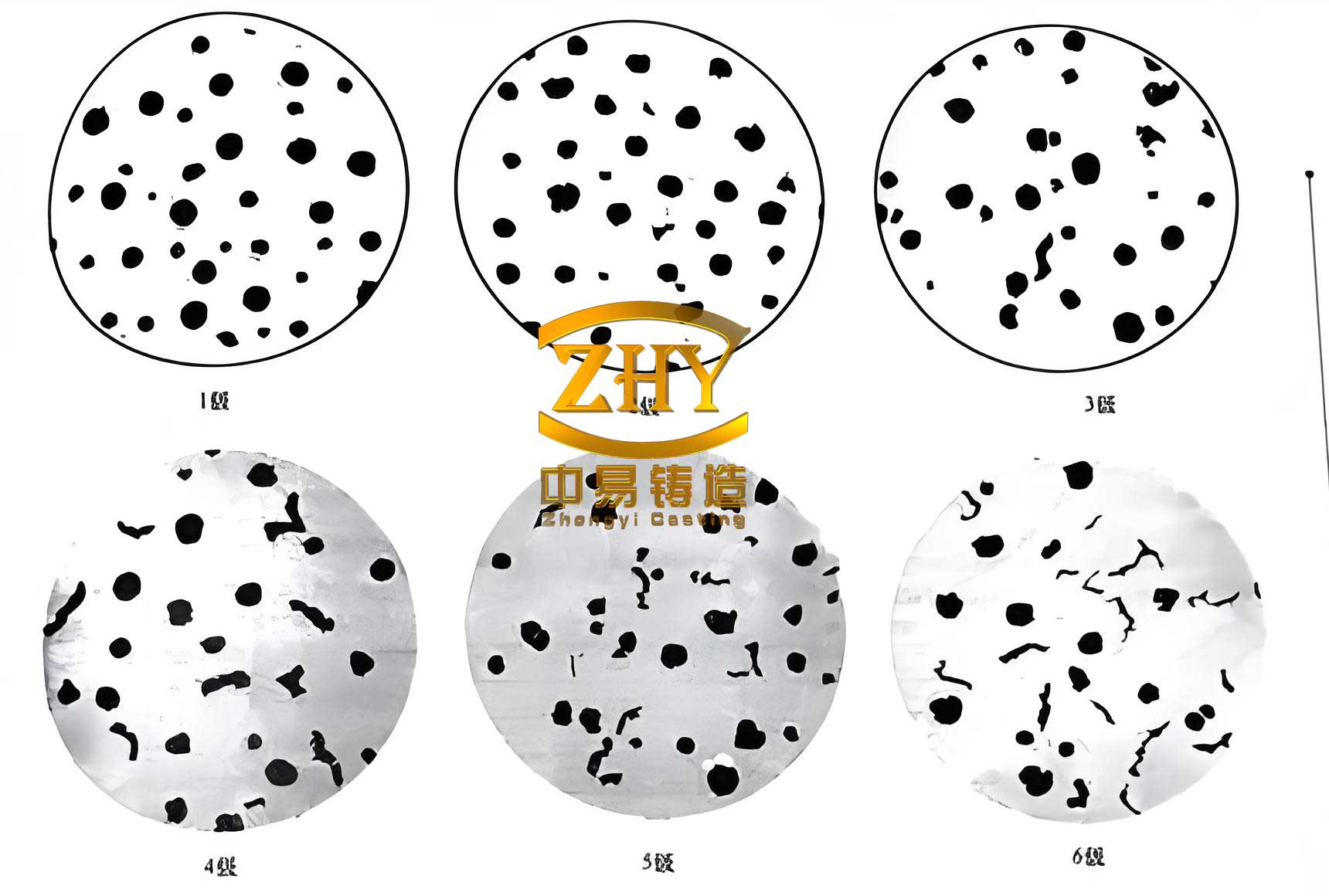
The results from this first trial were unsatisfactory, confirming the difficulty of heavy-section production. While the surface and mid-radius regions showed acceptable nodularity (Grade 2-3), the core of the test block exhibited severe chunk graphite (Grade 5). This was directly reflected in the poor mechanical properties.
| Sample Location | Tensile Strength (MPa) | 0.2% Proof Stress (MPa) | Elongation (%) | Hardness (HBW) |
|---|---|---|---|---|
| Upper (100mm) | 363 | 274 | 7.9 | 158 |
| Upper (200mm) | 357 | 272 | 6.3 | 161 |
| Upper (350mm) | 354 | 277 | 6.6 | 158 |
| Lower (100mm) | 359 | 261 | 7.7 | 157 |
| Lower (200mm) | 360 | 263 | 8.3 | 157 |
| Lower (350mm) | 354 | 263 | 7.5 | 158 |
| Sample Location | Nodularity (Edge) | Nodularity (Core) | Graphite Form (Core) |
|---|---|---|---|
| All Sections | Grade 2-3 | Grade 5 | Chunk Graphite |
Chemical analysis of drillings taken from the block’s surface and core revealed no significant macroscopic fading or segregation of magnesium or rare earths. This finding challenges the conventional wisdom that high residual magnesium is always necessary for heavy sections. In a low-sulfur iron (<0.02% S) within the reducing environment of the sand mold, the oxidation-driven fade of magnesium appears negligible.
The formation of chunk graphite in the core is attributed to a combination of factors intrinsic to slow solidification: a low undercooling ($\Delta T$), a scarcity of potent graphite nucleation sites, and the extended time for crystal growth. The undercooling is related to the cooling rate ($\dot{T}$) and the alloy’s composition. In heavy-section spheroidal graphite iron, the low cooling rate results in a small $\Delta T$, pushing solidification closer to equilibrium and favoring degenerate graphite forms. Furthermore, the prolonged solidification time allows for potential microsegregation of elements like Sb and RE, which can destabilize the austenite shell surrounding growing graphite nodules, leading to irregular growth.
Our improvement strategy targeted these root causes: enhancing nucleation, slightly modifying the driving force for graphite growth, and marginally increasing the solidification rate. The key adjustments were:
- Increased Carbon Equivalent: We raised the CE to 4.35-4.45% (C: 3.65-3.75%, Si: 2.10-2.25%) to increase the graphitization potential and the number of graphite particles, thereby reducing their growth time and size.
- Lower Pouring Temperature: Reduced to 1320 ±10 °C. This decreases the total heat content the mold must absorb, shortening the solidification time ($t_s$) as implied by the initial conditions in the Chvorinov equation.
- Enhanced Inoculation: The total inoculation amount was increased to 0.7-0.9%, firmly distributed across the three stages. This maximized the number of heterogeneous nucleation sites for graphite.
- Optimized Treatment: Nodularizer addition was fine-tuned for a treatment temperature of ~1450°C to ensure clean, efficient reaction without excessive fade.
The results from the modified process were markedly successful. The mechanical properties improved dramatically, and critically, the nodularity was consistently Grade 2-3 throughout the entire section, including the core.
| Sample Location | Tensile Strength (MPa) | 0.2% Proof Stress (MPa) | Elongation (%) | Hardness (HBW) |
|---|---|---|---|---|
| Upper (100mm) | 390 | 251 | 17.0 | 148 |
| Upper (200mm) | 394 | 252 | 23.5 | 144 |
| Upper (350mm) | 390 | 254 | 18.5 | 145 |
| Lower (100mm) | 385 | 255 | 17.5 | 146 |
| Lower (200mm) | 394 | 255 | 18.5 | 144 |
| Lower (350mm) | 384 | 264 | 20.5 | 148 |
| Sample Location | Nodularity (All Regions) | Graphite Size | Pearlite Content |
|---|---|---|---|
| All Sections | Grade 2-3 | Grade 6 | < 5% |
This investigation yields several critical insights for producing heavy-section spheroidal graphite iron castings. First, chunk graphite is a prevalent risk even at moderate silicon levels and must be proactively addressed. Second, a higher carbon equivalent than traditionally used for thinner sections is beneficial, as it increases graphite count and reduces undercooling, moving the system away from conditions favoring chunk graphite. The risk of exploded graphite at higher CE is managed by controlling the pouring temperature and inoculation. Third, vigorous, multi-stage inoculation is non-negotiable to provide a high density of nucleation sites that survive the long solidification interval. Fourth, a lower pouring temperature effectively shortens the solidification time, improving the cooling rate in the mold. Fifth, for low-sulfur base iron, excessively high residual magnesium is unnecessary and may even be detrimental; a level of 0.035-0.045% is sufficient for stable spheroidization in heavy sections.
The microstructure of high-quality spheroidal graphite iron is characterized by well-formed, discrete graphite nodules embedded in a metallic matrix, which is typically ferritic, pearlitic, or a mixture, as shown in the micrograph below. Achieving this structure in heavy sections requires precise control over all the factors discussed.
From a theoretical perspective, the success of our modifications can be linked to fundamentals of solidification. The increase in CE raises the equilibrium eutectic temperature ($T_{eut}$), which for the Fe-C-Si system can be approximated by:
$$ T_{eut} (°C) \approx 1153 + 5.25 \cdot \%Si – 30 \cdot \%P $$
A higher $T_{eut}$ for a given pouring temperature slightly increases the undercooling ($\Delta T = T_{eut} – T_{nuc}$) if nucleation temperature remains similar, promoting a finer eutectic structure. More importantly, the increased graphite count ($N$) reduces the average diffusion distance for carbon atoms to each growing nodule. The final nodule radius ($r$) is related to the number of nuclei and the total carbon available for the eutectic reaction, which can be conceptually linked by a simplified relation: $r \propto (1/N)^{1/3}$. Therefore, by maximizing $N$ through intensive inoculation, we limit the size to which individual nodules can grow, preventing the breakdown into chunk graphite. The combination of these principles—control of thermal conditions, chemistry, and nucleation—provides a robust framework for consistently producing high-nodularity, heavy-section spheroidal graphite iron castings with reliable mechanical properties.