
In my years as a foundry engineer, I have witnessed the transformative power of the automotive industry on shell casting processes. The relentless demand for lighter, stronger, and more reliable components pushes our craft to its limits. A particularly vivid chapter in this ongoing evolution was the challenge presented by the MQSP5077-11 water pump housing. This shell casting, destined for rigorous markets in North America and Europe, was not just another part; it was a testament to our capability to deliver precision under pressure. Its success or failure hinged on our ability to conquer persistent surface defects that marred its critical, non-machined surfaces. This is the story of that conquest, moving from a disheartening scrap rate to a triumph of applied solidification science.
The initial production run was fraught with quality issues that threatened the entire project. The shell castings exhibited severe surface defects: shrinkage cavities surrounded by a honeycomb of micro-porosity, heavy slag inclusions on the top surfaces, and disfiguring flow marks or “fold” defects reminiscent of misruns in investment casting. These were not minor blemishes. The slag and folds were located on non-machined aerodynamic surfaces of the internal water passages, making them unacceptable. Furthermore, the shrinkage posed a risk to the pressure-tightness and structural integrity of the final machined part. The initial scrap rate hovered around a crippling 37%, a clear indicator that the existing process was fundamentally flawed.
A deep dive into the initial process revealed its shortcomings. The pump housing is a complex, thin-walled shell casting with an irregular internal cavity. Key specifications were demanding:
| Parameter | Specification / Target |
|---|---|
| Material (Equivalent to ANSI No. 40) | HT250-HT300 |
| Tensile Strength | > 276 MPa |
| Hardness | 190 – 250 HB |
| Pearlite Content | > 85% |
| Major Wall Thickness | 7.8 mm ± 1 mm |
| Surface Finish (As-Cast) | Smooth, clear contours, free from defects |
The original gating system was a simple, partially closed design with three ingates along one of the long sides of the rectangular casting. My analysis pointed to several root causes for the failure. First, the multiple, closely spaced ingates caused a dispersed, turbulent flow front. The initial, cooler metal entering the mold cavity, laden with oxides and gases from the reaction with the resin-coated sand cores, was not efficiently evacuated. Instead, it was trapped along the upper reaches of the mold cavity, solidifying into slag patches and cold folds. Second, the thermal profile was wrong. The gating concentrated heat in one area, while the opposite, far end of the shell casting remained a “cold spot,” promoting premature solidification that blocked the escape of gases and late-arriving metal, leading to surface imperfections. We tried adjustments—increasing ingate size, reducing their number—but these were mere permutations of a broken model. The defects persisted because we were not managing the dynamics of filling and solidification holistically.
The breakthrough came from applying the principles of Equilibrium Solidification Technology. This philosophy moves beyond simple directional solidification. It emphasizes the precise control of thermal gradients and feeding paths to accommodate both liquid contraction during cooling and graphitic expansion during eutectic solidification. For thin-walled, complex shell castings like our pump housing, the key is to ensure a smooth, coherent metal front that pushes impurities ahead of it, not trapping them within.
The core of the new design was the strategic use of an overflow runner. The principle can be summarized as creating a controlled, sacrificial exit for the “bad” metal—the first, cold, oxide-laden portion of the stream. We completely redesigned the gating. Following the “large orifice outflow” theory, we placed two well-sized ingates at optimized positions along the casting’s centerline to promote rapid and even filling. Most critically, at the highest point on the opposite side of the casting—precisely where cold metal and gases accumulated—we installed a thin, wide overflow.
The design parameters for this critical element were calculated based on the modulus of the section it was intended to drain. The modulus $M_c$ of a casting section is given by its Volume $V$ to its cooling surface area $A_s$:
$$ M_c = \frac{V}{A_s} $$
The overflow neck needed to freeze after the metal in the problem area of the shell casting but before the ingates, ensuring it acted as a sink, not a feeder. Its dimensions were precisely set:
$$ \text{Neck Thickness} = 3 \text{ mm}, \quad \text{Neck Width} = 42 \text{ mm} $$
This shallow, wide channel provided minimal thermal mass to freeze quickly, but ample area to collect and trap the initial, contaminated flow.
The revised process parameters are summarized below, contrasting with the old approach:
| Process Parameter | Original (Defect-Prone) Process | Optimized (Equilibrium Solidification) Process |
|---|---|---|
| Gating Philosophy | Closed/Partially Closed, Multiple Points | Controlled Open with Strategic Overflow |
| Ingate Number & Placement | 3, along one side | 2, centered for coherent front |
| Overflow | None | Yes, at highest opposite point |
| Pouring Temperature | > 1360°C | > 1360°C (with stricter front control) |
| Mold Preparation | Standard venting | Aggressive top coat venting (pinholes) |
| Core Gas Management | Assumed adequate | Proactive (low-temp core drying <50°C) |
This integration of gating design and overflow technology fundamentally changed the physics inside the mold. The metal now filled the cavity as a unified, advancing front. The cold, dirty first metal was naturally channeled into the overflow, effectively “cleansing” the main shell casting cavity. Furthermore, this passage provided an excellent escape route for gases generated by the resin-coated sand cores, preventing gas bubbles from being trapped against the upper mold surface and creating pinholes or blisters.
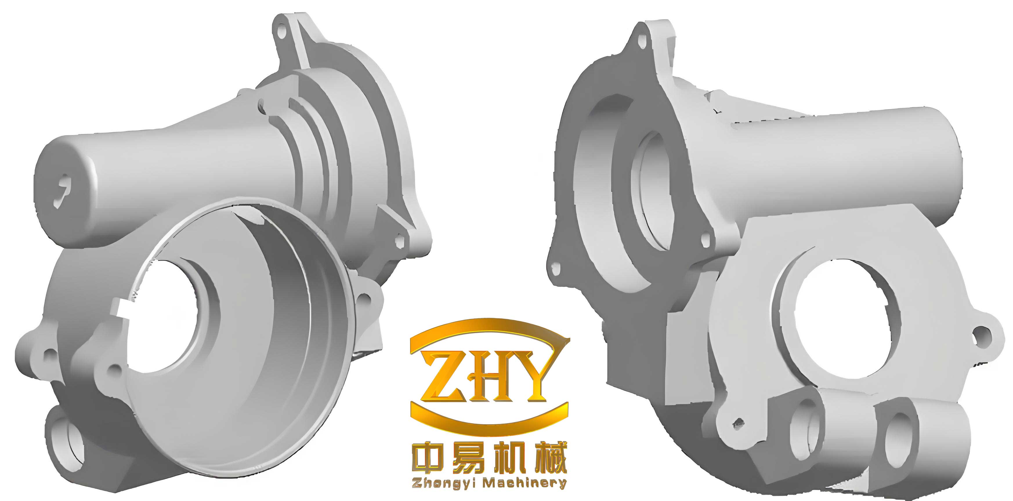
The results were not incremental; they were transformative. The scrap rate attributed to surface defects—slag, folds, cold shuts, and associated shrinkage—plummeted from 37% to approximately 4%. The surface quality of the shell castings achieved the required smoothness and clarity. Internal soundness improved dramatically, leading to consistent pressure-tightness during the mandatory air-pressure tests. The mechanical properties, always within spec, now showed even greater consistency from casting to casting.
| Quality Metric | Before Optimization | After Optimization |
|---|---|---|
| Scrap Rate (Surface/Flow Defects) | ~37% | ~4% |
| Surface Finish (Visual Inspection) | Unacceptable (Slag, Folds) | Fully Acceptable |
| Pressure Test Yield | Inconsistent, often failing | Consistently High (>99%) |
| Dimensional Stability | Variable due to uneven cooling | Highly Consistent |
This case study reinforces several universal principles for high-quality shell castings, particularly for the automotive sector:
1. The Overflow is a Non-Negotiable Tool for Premium Surfaces: For shell castings with large, flat areas or complex internal geometries, an overflow is not a “band-aid”; it is an essential design feature. It solves multiple problems simultaneously: venting gases, eliminating cold metal, and reducing turbulence. Its placement must be at the highest point of the mold cavity relative to the ingates to function correctly.
2. Process Refinement is Holistic: Success cannot rely on a single “silver bullet.” The optimized gating worked synergistically with other refined practices:
* Mold Venting: Adding explicit vent holes in the cope above problem areas provides an extra escape path for core and mold gases.
* Metal Cleanliness: While the overflow helps, starting with clean metal is paramount. Proper slag skimming, the use of pouring filters in the gating system, or even a sprinkle of slag coagulant on the ladle can make the overflow’s job easier and more effective.
* Core Process Control: Ensuring cores are adequately but not excessively dried (<50°C) minimizes sudden, violent gas generation during pouring, which can overwhelm even a well-designed system.
3. The Mathematics of Modulus Guides Design: Applying calculations like modulus comparisons between the casting section, the ingate, and the overflow neck ensures each freezes in the correct sequence. This scientific approach replaces guesswork with predictable engineering. The patternmaker’s shrink allowance, which we carefully applied as 1.5% on the long axis and 1.0% on the width, is another example of such precision:
$$ \text{Pattern Allowance}_{long} = L_{pattern} \times 0.015 $$
$$ \text{Pattern Allowance}_{width} = W_{pattern} \times 0.010 $$
4. Pouring Dynamics are Critical: The empirical rule for pouring time $t_p$ in seconds for gray iron, often related to the casting weight $W$ in kg, must be balanced against flow stability. While a fast pour ($t_p$ ~ 6-9 seconds for this ~14kg casting) is needed to prevent mistuns, the velocity must be controlled to avoid erosion. The cross-sectional area of the gating system directly governs this velocity. A common starting point is the empirical relationship:
$$ t_p = k \cdot \sqrt[3]{W} $$
where $k$ is a factor typically between 1.7 and 2.2 for steel and iron, adjusted based on section thickness. For our thin-walled shell castings, we aimed for the lower end of the time range to ensure complete filling before the metal lost its fluidity.
The lessons from optimizing this automotive water pump housing extend far beyond a single part number. They form a blueprint for tackling high-integrity shell castings across industries. Whether it’s compressor bodies, hydraulic valve manifolds, or transmission housings, the core challenges remain: achieving pressure-tightness, superior surface finish, and dimensional accuracy in complex, thin-walled geometries.
Looking forward, the principles of controlled filling and thermal management dovetail perfectly with advanced simulation software and emerging technologies. Modern casting simulation allows us to virtually test gating and overflow designs, visualizing metal flow, temperature gradients, and potential defect formation before a single pattern is cut. This digital foundry approach, guided by the hands-on wisdom of equilibrium solidification principles, represents the future. Furthermore, the use of advanced inorganic binders for cores, which generate far less gas, can reduce the gas-related challenges, making the production of flawless shell castings even more robust.
In conclusion, the journey from a 37% scrap rate to a reliable, high-quality production process for the MQSP5077-11 housing was a powerful validation of foundational foundry science applied with precision and insight. It underscored that in the demanding world of automotive shell castings, quality is not an accident. It is the direct result of understanding and controlling the intricate dance of fluid dynamics, heat transfer, and solidification shrinkage. By mastering these elements—through strategic gating, purposeful overflows, and meticulous process control—we can consistently produce shell castings that are not just components, but reliable foundations for modern machinery.