
In my extensive experience within the heavy casting industry, particularly focusing on components for renewable energy, the production of high-integrity nodular cast iron (ductile iron) castings for wind turbines presents a significant and recurring challenge: shrinkage porosity. Wind turbine components such as hubs, main frames, bearing housings, and gearbox casings are subjected to extremely demanding service conditions, including high dynamic loads, impact, and sub-zero temperatures. These parts require excellent mechanical properties, good toughness at low temperatures, and superior vibration damping capabilities. Nodular cast iron, with its unique combination of high strength, good ductility, fatigue resistance, and castability, is ideally suited for these applications. However, the very solidification characteristics that give ductile iron its desirable properties also predispose it to the formation of shrinkage defects, which are often microscopic and internal, evading visual detection but drastically reducing mechanical performance. It has been documented that shrinkage porosity can reduce tensile strength by approximately 60% and fatigue strength by 40-50%. Therefore, a profound understanding of the root causes and the implementation of a robust, multi-faceted prevention strategy are paramount for ensuring the structural reliability and longevity of wind turbines.
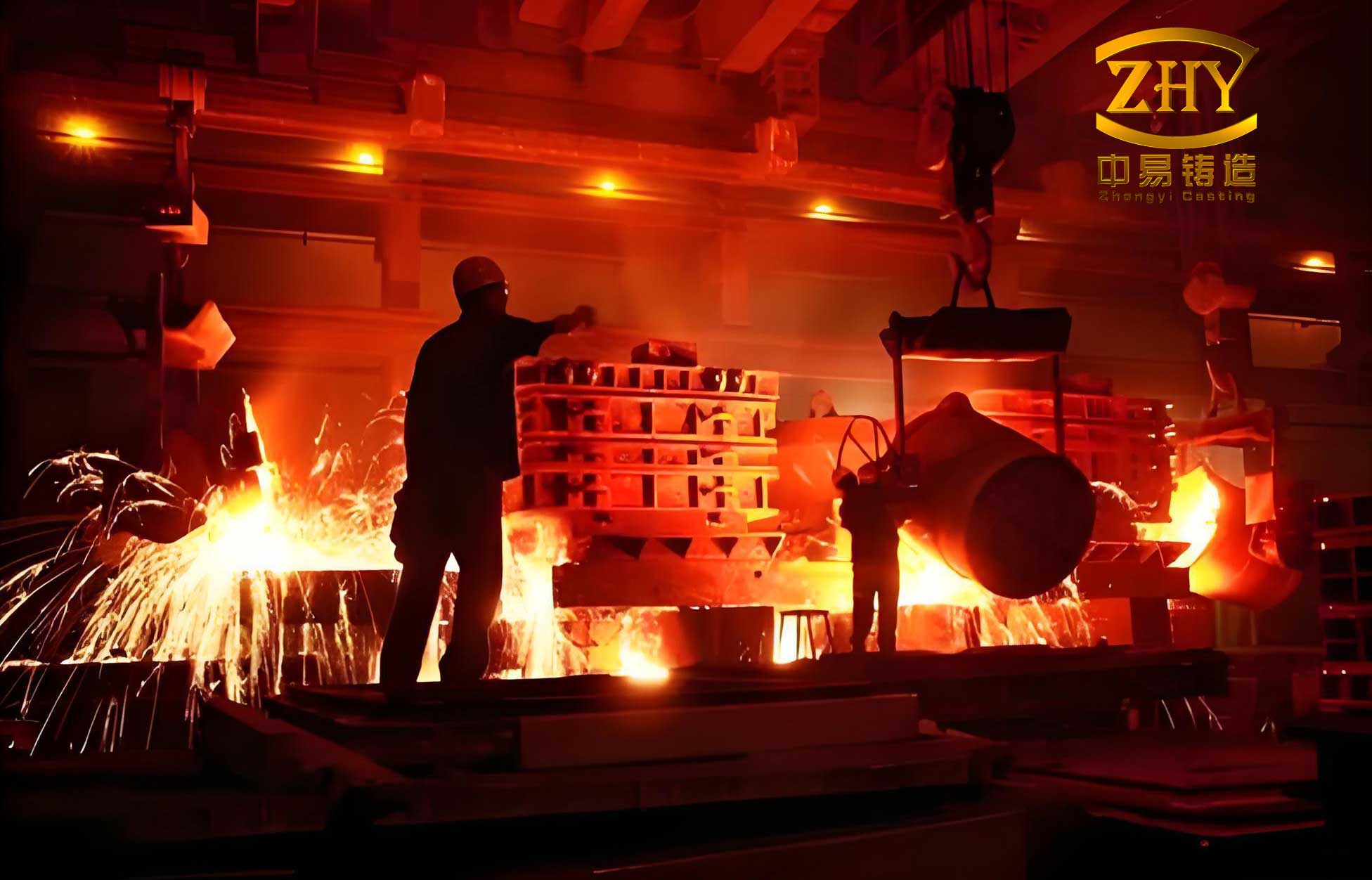
The fundamental issue lies in the “mushy” or pasty solidification mode of nodular cast iron. Unlike gray iron, which solidifies with a well-defined austenite-graphite eutectic front, ductile iron solidifies through the formation of numerous, discrete graphite spheroids surrounded by austenite shells. This leads to a prolonged eutectic freezing range and a significant expansion pressure due to graphite precipitation. This expansion can sometimes compensate for the liquid and solidification shrinkage, but when not properly controlled, it leads to the formation of dispersed microshrinkage or macroshrinkage cavities. The problem is exacerbated in large, heavy-section castings like those for wind turbines, where thermal gradients are difficult to manage. Our analysis must therefore be systematic, examining every stage from metallurgy to molding and pouring.
1. Comprehensive Analysis of Shrinkage Porosity Origins
The formation of shrinkage defects in wind turbine nodular cast iron castings is seldom due to a single factor. It is typically the consequence of interactions between several variables. We can categorize the primary influencing factors into five core areas.
1.1 Casting Design and Geometry
The geometry of a wind turbine component is often complex, featuring significant variations in wall thickness—from 60 mm to over 120 mm—and weights exceeding 30 tonnes. These geometric features inherently create “hot spots” or thermal centers that are last to solidify.
- Heavy Sections: Thick walls create a large thermal mass. While the surface cools rapidly to form a solid shell, the interior remains liquid for an extended period. The subsequent liquid and solidification contraction in this isolated liquid pool cannot be fed from the already solid outer shell, leading to internal shrinkage porosity. The severity can be estimated by considering the modulus (Volume/Surface area) of the section; a higher modulus indicates a slower cooling rate and a higher feeding demand.
- Junctions and Transitions: Areas where walls intersect (e.g., rib junctions, flange-to-body transitions) create isolated thermal centers. Even if a riser is placed nearby, the “feeding path” may be cut off by premature solidification at the junction’s periphery, leaving an isolated liquid pool that forms shrinkage.
The design challenge is to identify these hot spots early, often using modulus calculations: $$ M = \frac{V}{A} $$ where \( M \) is the modulus (cm), \( V \) is the volume (cm³), and \( A \) is the surface area (cm²). Sections with a high \( M \) value require special attention for feeding.
1.2 Sand Mold Properties and Stability
The mold is not a passive container; it dynamically interacts with the molten metal. For large nodular cast iron castings, the mold’s behavior during pouring and solidification is critical.
- Mold Wall Movement: This is a primary cause of shrinkage in ductile iron. The high graphite expansion pressure during eutectic solidification can push the mold walls outward if they lack sufficient strength and rigidity. This increases the internal volume of the mold cavity, creating an unexpected demand for additional feed metal which the risers cannot supply, resulting in shrinkage. The phenomenon is more pronounced with green sand molds but is also relevant to chemically-bonded sands like furan resin if compaction is inadequate.
- Sand Properties: Key properties include:
- High-Temperature Strength: The sand must resist deformation under the static head pressure of the metal and the expansion pressure.
- Low Thermal Deformation: The sand should minimize expansion and contraction when heated to avoid creating gaps or stresses that affect solidification.
- Permeability and Moisture Content: In bonded sands, low moisture is essential. High moisture creates a thick vapor zone, reducing the effective strength of the sand layer adjacent to the metal and promoting wall movement.
A stable, high-strength, and dry mold is the first line of defense against shrinkage defects originating from mold yield.
1.3 Gating and Feeding System Design
The design of the gating (channels for metal entry) and risering (feed metal reservoirs) systems dictates the thermal gradients and solidification sequence.
- Gating Design Errors: Placing ingates in thick sections is a common error. The thick ingate itself becomes a hot spot, staying liquid longer than the surrounding casting. Under expansion pressure, metal can actually flow back from the casting into the gating system, creating a “suck-back” shrinkage cavity in the casting.
- Riser Efficacy: Risers must be correctly sized, located, and designed to remain molten longer than the casting section they are intended to feed. Key principles include:
- Riser Modulus: The riser’s modulus \( M_r \) must be greater than the modulus of the casting section \( M_c \) it feeds. A common rule is \( M_r = 1.2 \times M_c \).
- Feed Path: A directional solidification gradient must be established from the casting to the riser. This often requires the use of chills (metal or exothermic) on thicker sections of the casting to accelerate cooling and ensure the riser is the last point to solidify.
- Riser Neck Design: The neck must be designed to freeze after the casting hot spot but before the riser itself, to prevent “shrinkage pipe” from propagating into the casting.
| Design Flaw | Mechanism | Resulting Defect |
|---|---|---|
| Ingate in thick section | Creates local hot spot, reverse flow during expansion | Shrinkage at ingate junction |
| Undersized riser | Insufficient feed metal volume, freezes too early | Shrinkage in casting hot spot |
| Poor riser placement | No direct feed path to thermal center | Isolated shrinkage in junction |
| Missing riser insulation/ exothermic sleeve | Riser cools too quickly, losing feeding capability | General microshrinkage |
1.4 Metallurgical and Chemical Composition
The chemical composition of the nodular cast iron melt is the most powerful tool for influencing solidification behavior and shrinkage tendency.
- Carbon Equivalent (CE) and Carbon Content: Carbon promotes graphite precipitation. A higher carbon content (within limits) increases fluidity and the number of graphite nodules, which enhances the internal expansion pressure and can help reduce shrinkage. The Carbon Equivalent is calculated as: $$ CE = \%C + \frac{\%Si}{3} + \frac{\%P}{3} $$ For wind turbine grades like QT400-18AL-1, a CE between 4.3 and 4.5 is often targeted to balance shrinkage resistance and mechanical properties.
- Silicon (Si): Silicon is a strong graphitiser. However, for low-temperature impact grades, Si must be controlled (typically 1.8-2.3%) to prevent excessive embrittlement. Lower Si can slightly increase shrinkage tendency.
- Magnesium (Mg) and Rare Earths (RE): These are essential for spheroidization but are strong carbide stabilizers. Excess levels increase the chilling tendency and the amount of contraction during solidification, promoting shrinkage. Tight control is necessary (e.g., Mg: 0.035-0.06%, RE: 0.005-0.015%).
- Impurity Elements:
- Phosphorus (P): A highly detrimental element. It forms low-melting-point, brittle phosphide eutectic networks at grain boundaries, which widen the solidification range and severely impair feeding. Levels must be kept below 0.04%.
- Sulfur (S): Combines with Mg and RE, consuming nodularizing agents and promoting dross. It reduces fluidity. Levels must be kept very low, typically below 0.015%.
- Gas Content: High levels of dissolved gases (hydrogen, nitrogen) precipitate as bubbles during solidification, blocking the interdendritic channels through which feed metal must flow to compensate for shrinkage, thus creating gas-assisted shrinkage porosity.
| Element | Target Range (wt.%) | Rationale & Effect on Shrinkage |
|---|---|---|
| C | 3.75 – 3.95 | High C increases graphitization expansion, reduces shrinkage. Upper limit avoids graphite flotation. |
| Si | 1.8 – 2.3 | Promotes ferrite and graphite. Controlled for low-temperature toughness. Lower limit may increase shrinkage risk. |
| Mn | 0.1 – 0.3 | Low level to prevent pearlite stabilization and segregation. |
| P | ≤ 0.04 | Minimized to avoid phosphides and widened freezing range. |
| S | ≤ 0.015 | Minimized to reduce Mg/RE consumption and improve fluidity. |
| Mg | 0.035 – 0.060 | Essential for nodularization. Excess increases carbide formation and shrinkage. |
| RE (Ce, La) | 0.005 – 0.015 | Aids nodularization, controls trace element effects. Excess is harmful. |
1.5 Melting, Inoculation, and Pouring Practice
The final steps in the process chain have a decisive impact.
- Inoculation: This is the deliberate addition of materials (e.g., FeSi alloys containing Ca, Ba, Al) to melt just before casting to increase the number of graphite nucleation sites. Effective inoculation is critical:
$$ \text{Graphite Nodule Count} \propto \text{Inoculation Efficiency} $$
A high nodule count (\(>100 \text{ nodules/mm}^2\)) results in smaller, more closely spaced eutectic cells. This reduces the distance for carbon diffusion, promotes a more uniform and rapid austenite-to-ferrite transformation, and creates a smoother solidification front, all of which improve feeding and reduce shrinkage. Inadequate inoculation leads to fewer, larger nodules, carbides, and increased shrinkage. - Pouring Temperature:
- Too Low (e.g., < 1330°C): Reduced fluidity impairs the riser’s ability to feed distant sections. The metal may begin solidifying in the gating system.
- Too High (e.g., > 1380°C): Increases total liquid contraction volume. It also imposes a greater thermal load on the mold, potentially accelerating mold wall movement and sand burn-on, which can block permeability. The increased temperature differential can also lead to greater internal stresses.
An optimal range of 1340-1360°C is common for large nodular cast iron castings.
- Riser Topping: For open top risers, failing to top up with hot metal after pouring to compensate for initial liquid shrinkage significantly reduces the effective feed volume.
2. A Systematic Framework for Prevention and Control
Based on the above analysis, a successful strategy to eliminate shrinkage defects in wind turbine nodular cast iron castings must be holistic, integrating chemical, design, and process controls.
2.1 Advanced Foundry Methodology and Process Simulation
Modern foundries rely on digital tools to predict and correct issues before making molds.
- Solidification Simulation: Software like ProCAST, MAGMASOFT, or Flow-3D Cast is indispensable. These programs solve the fundamental equations of fluid flow, heat transfer, and solidification, including the specific volume changes associated with graphite expansion in nodular cast iron. They can predict the location of shrinkage porosity with high accuracy, allowing engineers to iteratively optimize riser and chill placement, gating design, and pouring parameters virtually. The use of such simulation is now considered a standard requirement for first-time-right production of costly wind turbine components.
- Molding Practice: For large castings, furan no-bake sand is typically chosen for its high strength, low moisture, and good dimensional stability. Rigorous control of sand properties (strength, compactability, LOI) and thorough mold/ core drying are essential to minimize wall movement.
- Chill Design: Strategic placement of internal (cast-in) or external chills is critical to control solidification direction. Chills are used to accelerate cooling in thick sections, creating a thermal gradient that directs shrinkage towards the riser. The chill size and capacity must be calculated based on the modulus of the hot spot it is intended to control.
2.2 Precision Metallurgical Control
This encompasses the entire melt journey from charge to ladle.
- Melting: Use of medium-frequency induction furnaces provides clean, homogeneous melting with good temperature control and reduced gas pickup compared to cupolas.
- Treatment: The nodularization process (typically using FeSiMg alloys in a tundish cover or flow-through process) must be consistent and well-controlled to achieve the target Mg recovery. Post-inoculation (late stream inoculation) is highly effective in maximizing graphite nodule count. A combination of pre-inoculation (in the ladle) and post-inoculation is often best.
- Process Monitoring: Real-time monitoring is key.
- Optical Emission Spectrometry (OES) for precise, frequent chemistry checks.
- Thermal Analysis: Using a small sample cup with a thermocouple provides a cooling curve that gives immediate information on carbon equivalent, inoculation efficiency, and graphite nucleation potential.
- Ultrasonic testing of melts for dissolved hydrogen.
| Process Stage | Control Parameter | Target / Limit | Monitoring Method |
|---|---|---|---|
| Melting | Final Furnace Chemistry | Per Table 2 (pre-treatment) | OES Spectrometer |
| Nodularization | Mg Residual | 0.035 – 0.060% | OES on treated sample |
| Inoculation | Inoculant Type & Amount | 0.2 – 0.6% post-inoculant | Weighing, controlled addition system |
| Pouring | Temperature | 1340 – 1360°C | Immersion thermocouple |
| Molding | Sand Compressive Strength | > 1.2 MPa (furan sand) | Sand tester |
2.3 Quality Verification and Feedback Loop
Preventive measures must be validated. Non-destructive testing (NDT) provides the final assurance.
- Ultrasonic Testing (UT): Per standards like EN 12680-3 (Grade 2), UT is used to detect internal discontinuities such as shrinkage cavities. Modern phased-array UT provides detailed imaging of defect size and location.
- Radiographic Testing (RT): X-ray or gamma-ray inspection provides a 2D image of the internal soundness, excellent for validating areas predicted to be at risk of shrinkage.
- Mechanical and Metallurgical Testing: Cast-on or separately cast test bars are machined and tested to verify the tensile strength, elongation, and impact energy (e.g., at -30°C). Microstructure evaluation (graphite nodularity >90%, ferrite >90%, carbides <1%) confirms the metallurgical quality. Any deviation from mechanical or microstructural targets can be a proxy for underlying shrinkage or other defects.
The data from NDT and mechanical tests must feed directly back into the process engineering and metallurgy teams to continuously refine the production parameters for nodular cast iron components.
3. Conclusion and Future Perspectives
The mitigation of shrinkage defects in large wind turbine nodular cast iron castings is a complex but manageable challenge. It requires a deep understanding of the material’s solidification science and a disciplined, integrated approach across design, molding, metallurgy, and process control. There is no single “silver bullet.” Success is achieved by:
- Designing castings and feeding systems based on thermal modulus analysis and validated by advanced solidification simulation.
- Employing stable, high-strength molding systems to resist wall movement.
- Exercising precise control over the chemical composition, particularly C, Si, Mg, and tramp elements like P and S.
- Implementing robust and efficient inoculation practices to ensure a high, fine graphite nodule count.
- Controlling pouring temperature and riser management practices.
- Establishing a closed-loop quality system using NDT and mechanical testing for verification and continuous improvement.
As wind turbines continue to increase in size and power rating, pushing the dimensions and requirements of nodular cast iron components further, the industry must continue to innovate. This includes developing even more predictive simulation tools that fully capture the complex interplay of expansion and shrinkage in nodular cast iron, advancing real-time process control and data analytics (Industry 4.0), and exploring new, enhanced inoculation technologies. By relentlessly focusing on these fundamental principles and embracing technological advancement, foundries can consistently produce sound, reliable nodular cast iron castings that meet the rigorous demands of the global wind energy sector.