
Abstract:
This article focuses on the cylinder block casting of an 11-liter 6-cylinder engine of a commercial vehicle. By systematically analyzing the flow and temperature fields of the original pouring system’s molten iron filling process, a new type of pouring system was designed. Through batch production verification, the local porosity defect of the casting was effectively solved. At the same time, the gate position was improved to avoid heat buildup in the tile seat area, and the material performance of the casting tile seat area was improved.
1. Basic Information of the Casting
The 11-liter cylinder block produced by our company is a straight-6 cylinder engine block with a cylinder block material requirement of HT250 and a casting weight of approximately 240 kg. The main wall thickness is 5 mm. Clay green sand and HWS static pressure molding are used, with horizontal pouring and one casting per mold. The molten iron is melted in a medium-frequency induction furnace and poured using a KW pouring machine at a pouring temperature of 1440 °C ± 10 °C, with a pouring speed of approximately 14-17 kg/s.
The pouring system is designed with a runner, seven vertical gates, and three layers of ingates. The ingates are set on the two-layer crankshaft bearing caps of the cylinder block and the oil pan flange of the lower box. The original design intention was to achieve a relatively stable filling process, with each gate receiving a basically uniform amount of molten iron.
However, two main issues often arise during actual production: ①孔洞 defects occur in the crankcase area of the upper box; ②The mechanical properties of the crankshaft bearing cap area are on the lower limit. The following text will analyze these two issues.
2. Distribution, Morphology, and Analysis of Defects
2.1 Location of Defects
Hollow defects frequently appear near the crankcase of the upper box of this 11-liter cylinder block casting, mainly occurring in the thin-walled areas at the highest point .
2.2 Macroscopic Morphology of Defects
The defect morphology is spherical, with smooth walls. Minor defects can be repaired by welding, while severe defects lead to wall penetration and scrap.
2.3 Microscopic Analysis of Defects
2.3.1 Metallographic Structure Analysis of Defective Areas
The graphite morphology near the defect under a metallographic microscope is a combination of flake graphite and fine punctate graphite. Further analysis is needed to determine the specific type of pore defect.
2.3.2 Scanning Electron Microscope (SEM) Analysis of Defective Areas
Microscopic morphology analysis was conducted on dissected defects using a scanning electron microscope and energy dispersive spectrometer. The energy dispersive spectrometry (EDS) images of the defective area at 45× and 90× magnification, respectively. The interior of the defect is very smooth, with a waist-circular cross-section accompanied by obvious pores. Table 1 lists the elemental content detected by EDS. The weight percentage of oxygen locally reaches 30.48%, with the remainder being carbon and iron. Therefore, it can be determined that this is a porosity defect.
Table 1: Elemental Content at the Defective Location
| Element | Element Concentration | Intensity Correction | Weight Percentage | Weight Percentage Sigma | Atomic Percentage |
|---|---|---|---|---|---|
| C K | 12.56 | 3.7006 | 3.93 | 0.11 | 9.18 |
| O K | 30.48 | 1.2316 | 28.63 | 0.28 | 50.19 |
| Na K | 0.65 | 0.7010 | 1.07 | 0.09 | 1.31 |
| Mg k | 0.21 | 0.6640 | 0.37 | 0.06 | 0.43 |
| Al K | 3.05 | 0.7758 | 4.55 | 0.08 | 4.73 |
| Si K | 3.43 | 0.8476 | 4.69 | 0.08 | 4.68 |
| P K | 0.48 | 1.2390 | 0.45 | 0.05 | 0.41 |
| S K | 1.05 | 0.9774 | 1.24 | 0.05 | 1.09 |
| K K | 1.21 | 1.1357 | 1.23 | 0.06 | 0.88 |
| Ca K | 1.23 | 1.0868 | 1.31 | 0.06 | 0.92 |
| Ti K | 4.20 | 0.9255 | 5.25 | 0.12 | 3.07 |
| Cr K | 1.13 | 0.9557 | 1.36 | 0.10 | 0.74 |
| Mn K | 3.54 | 0.8756 | 4.68 | 0.15 | 2.39 |
| Fe K | 30.75 | 0.9984 | 35.63 | 0.29 | 17.90 |
| Ni K | 2.65 | 0.8695 | 3.53 | 0.19 | 1.68 |
| Ce L | 1.54 | 0.8544 | 2.09 | 0.23 | 0.42 |
| Total | 100.00 |
3. Causes of Porosity Defects
Porosity typically occurs in the upper thin-walled sections of castings, the highest points of castings, etc. The porosity defects in this case are located on the upper surface of the casting at the highest point. Most porosity is spherical, but irregular morphologies can also occur, with occasional metallic iron particles inside the pores.
Common causes of porosity include: low pouring temperature; poor exhaust venting in the casting; casting runner clogging the exhaust vent; and an unreasonable pouring system design leading to the collection of cold molten iron.
Based on the possible causes of porosity, we conducted a tracking analysis of the cylinder block production process:
- Porosity: The actual production process uses a KW pouring machine with an initial pouring temperature of 1440 °C. Each ladle of molten iron is poured into eight molds, with each pouring taking approximately six minutes. After actual measurement, the temperature drop per minute during pouring with the KW machine is approximately 3.3 °C, resulting in a pouring temperature of approximately 1420 °C for the last mold. The pouring temperature is reasonable, and the temperature drop has little impact on porosity, so it is deemed a non-essential factor.
- Poor exhaust venting in the casting: During the pouring process, it was confirmed that the ventilation needles in the casting vent smoothly, and the ventilation needles showed normal firing, so it is deemed a non-essential factor.
- Casting runner: After observing the sand stripping and shaking out of the casting, it was confirmed that there was no molten iron leakage during the pouring process, so it is deemed a non-essential factor.
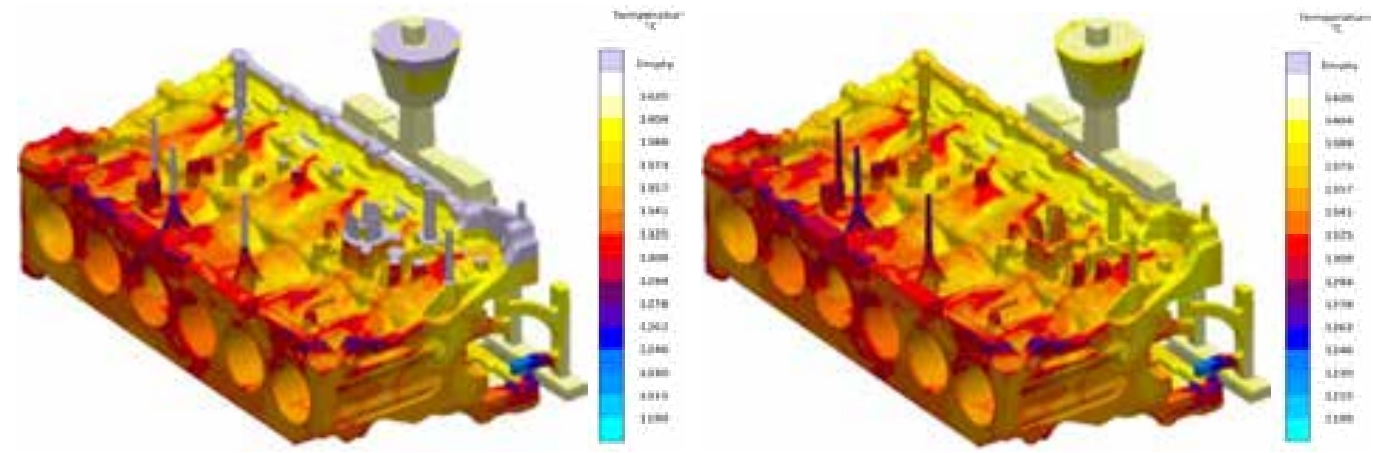
- Unreasonable pouring system design leading to the collection of cold molten iron: CAE filling simulation analysis revealed that the first flow of cold molten iron collects in the crankcase area (upper box), leading to porosity. This is identified as the primary cause. The detailed analysis process is as follows.
The liquidus temperature of molten iron with different compositions varies. After multiple measurements, the liquidus temperature of this 11-liter cylinder block was found to be 1230 °C.