
1. Technical Requirements
1.1 DIFF Case Specifications
| Specification | Details |
|---|---|
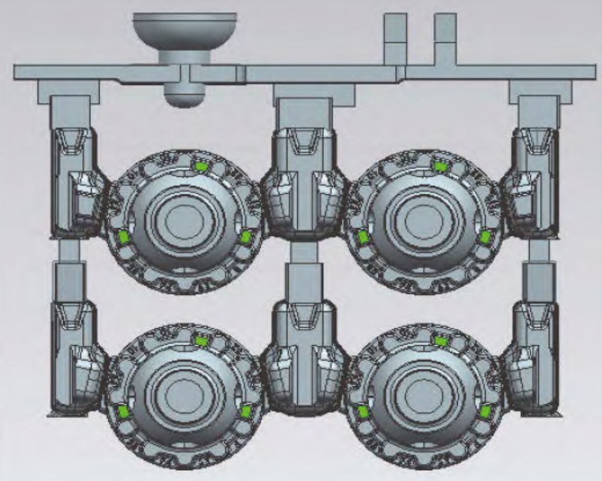
| Appearance | As shown in Fig. 1, with 4 windows and 3 pinholes, 3 asymmetric bosses on the flange face |
| Weight | Design weight of finished product: 2.32 kg, The design weight of a single blank piece is 3.32 kg |
| Material | QT600 – M (enterprise standard), chemical composition as in Table 1 |
| Tolerance & Defect | As in Table 2 |
| Metallographic & Property | As in Table 3 |
1.2 Chemical Composition (Mass Fraction, %)
| Element | Range |
|---|---|
| S | 0.02 |
| Si | 1.8 – 3.0 |
| Mn | 0.2 – 1.0 |
| P | ≤0.06 |
| Cu | 0.2 – 1.0 |
| Ti | 0.06 |
| Sn | 0.06 |
| Mg | 0.027 – 0.06 |
1.3 DIFF Case Dimensional Tolerances and Defect Requirements
| Tolerance/Defect Type | Specification |
|---|---|
| Casting Dimension Tolerance (mm) | ISO 8062 – CT9 |
| Casting Profile Tolerance (mm) | 2 (±1) |
| Defect Requirements – Appearance | Key machining surface: ≤1mm diameter and depth defects; Non – key machining surface: ≤3mm diameter and depth defects; Blank surface: ≤4mm diameter and depth bottom – visible hole – like defects |
| Defect Requirements – Internal | Porosity meets D3/1, X – ray flaw detection meets ASTM E – 446 ≤ level 2 |
1.4 Microstructure and Mechanical Properties Requirements
| Property | Requirement |
|---|---|
| Tensile Strength (MPa) | 650 |
| Yield Strength (MPa) | 405 |
| Elongation (%) | 3 |
| Hardness (HBW) | 200 – 265 |
| Spheroidization Rate (%) | 80 |
| Graphite Type | V + VI |
| Pearlite (%) | 55 |
| Carbide and Eutectic Phosphorus (%) | – |
2. Process Scheme
2.1 Risers and Gating System
- Riser Design: 2 castings with 3 risers. Single – use riser size: 120 mm×43 mm×50 mm, neck height 7.7 mm, length 55 mm, area 423 mm². Common riser size: 120 mm×55 mm×50 mm. Risers with weight reduction and separation features.
- Gating System: Spliced design with multiple lap joints for flow and slag control. Inner runner enters from the bottom of the riser.
2.2 Shrinkage Prevention Measures
- Axis Head Filling: Fill 60% of the axis head height (29 mm out of 48 mm total). Inner diameter ϕ39 mm formed by outer mold with 14 mm and 15° draft.
- Flange Thickness Subsidy: 0.5 mm thickness subsidy at the flange near the riser.
- Cold Needle Setting: ϕ6 mm×25 mm cold needle with 3° draft at the pinhole (later canceled).
2.3 Simulation Results and Adjustments
- Initial Simulation: Shrinkage at pinhole (2.6 mm³ and 11.0 mm³), flange (0.7 mm³), and axis head (removable by machining).
- Adjusted Scheme: Rotate casting 90°, no shrinkage at pinhole, axis head shrinkage 77.8 – 80.00 mm³ (machinable).
3. Sample Trial and Improvement
3.1 Trial Results
- Detection Results: Appearance, dimension, full – mold material, porosity, X – ray, and CT all qualified.
- Problem: Long and unstable pouring time (13 – 16 s), affecting production rhythm. Low process yield (36.7%).
3.2 Improvement Measures
- Exhaust Improvement: Add exhaust sheets at the horizontal runner with separation blocks at the bottom.
- Gating System Optimization: Cancel two vertical runners, reduce horizontal runner weight, inner runner enters from the top of the riser with lap joint.
3.3 Improvement Results
- Pouring Time: Simulated 8.539 s, actual 10.2 – 10.3 s, meeting production rhythm.
- Process Yield: Increased from 36.7% to 42.7%.
4. Conclusion
- Trial Product Quality: No shrinkage and porosity defects by X – ray, good appearance.
- Mass Production Quality: In a certain month, 1887 pieces inspected, 62 rejects, with a qualified rate of 96.71%. Defect details as follows:
| Defect Type | Quantity | Rejection Rate |
| Sand Hole | 37 | 1.96% |
| Impact Damage | 18 | 0.95% |
| Unclear Casting Mark after Shot Blasting | 7 | 0.37% |
| Client – side Processing Reject Rate | <1% | — |