
In the field of aerospace engineering, shell castings play a critical role as key components in aero-engines, where they must withstand extreme temperatures and stresses. This article delves into the investment casting process for K403 high-temperature alloy shell castings, focusing on overcoming common defects such as porosity, cold shuts, dimensional inaccuracies, and deformation. Based on my research and experience, I will outline the structural challenges, detail optimized process parameters, and validate the improvements through experimental results. The goal is to provide a comprehensive guide for enhancing the quality and reliability of such shell castings in production.
The shell castings in question are typically manufactured using K403 alloy, a nickel-based superalloy known for its high-temperature strength but prone to issues during solidification. The alloy composition, as shown in Table 1, includes elements like chromium, cobalt, and tungsten to enhance performance. However, the complex geometry of these shell castings—with varying wall thicknesses, tall pillars, and multiple hot spots—poses significant hurdles in achieving defect-free parts. In initial trials, these shell castings exhibited unstable metallurgical quality and severe dimensional deviations, prompting a thorough investigation into the entire investment casting workflow.
| Element | Content |
|---|---|
| C | 0.11–0.18 |
| Cr | 10.00–12.00 |
| Co | 4.50–6.00 |
| W | 4.80–5.50 |
| Mo | 3.80–4.50 |
| Ti | 2.30–2.90 |
| Al | 5.30–5.90 |
| Ce | ≤ 0.01 |
| Fe | ≤ 2.00 |
| Si | ≤ 0.50 |
| Mn | ≤ 0.50 |
| S | ≤ 0.01 |
| P | ≤ 0.02 |
| Ni | Balance |
The structural complexity of these shell castings is a primary concern. With dimensions like a 129 mm pillar height and wall thicknesses ranging from 6.5 mm, the part features numerous thermal junctions that exacerbate solidification issues. This leads to three main technical challenges: difficulty in wax pattern removal and dimensional stability, susceptibility to mold cracking and flash during pouring, and a high risk of defects like porosity, cracks, and cold shuts due to poor filling and heat dissipation. Addressing these requires a holistic approach across pattern making, shell building, and melting-pouring stages.
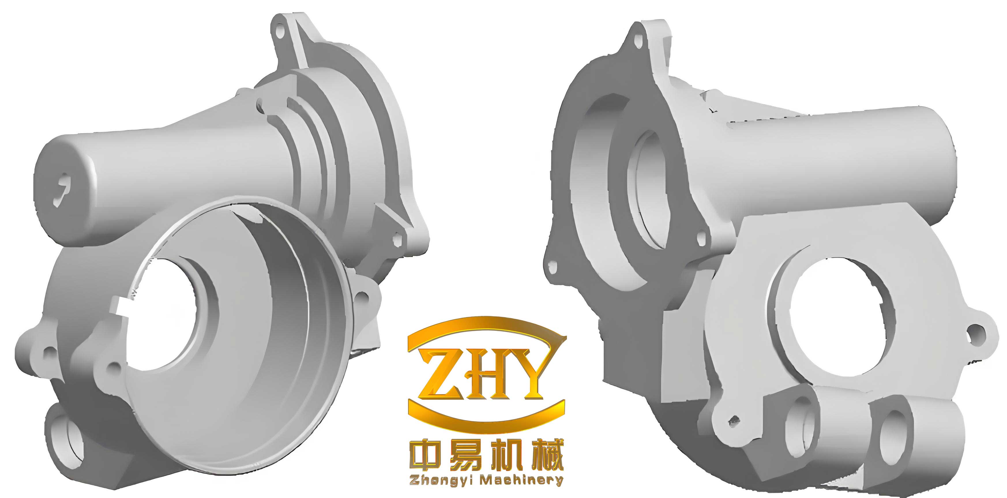
In pattern making, controlling the wax injection process is crucial for producing high-quality patterns that directly influence the final shell castings. Key parameters include wax temperature, mold temperature, injection pressure, and holding time. From my experiments, I found that a wax temperature of 55–63°C ensures adequate fluidity without excessive shrinkage, while a mold temperature of 25–35°C prevents defects like cold flow or sticking. The injection pressure, set at 15–25 bar, must be optimized to balance dimensional accuracy and surface finish; too high pressure can cause gas entrapment, whereas too low leads to incomplete filling. The holding time of 15–20 s helps reduce shrinkage, as described by the equation for volumetric change during solidification: $$ \Delta V = \beta V_0 \Delta T $$ where $\Delta V$ is the volume change, $\beta$ is the coefficient of thermal contraction, $V_0$ is the initial volume, and $\Delta T$ is the temperature drop. This principle is vital for minimizing distortions in shell castings.
Initially, wax patterns were produced in three separate sections and assembled using fixtures, but this method introduced human errors, causing dimensional offsets of up to 2.2 mm in critical features like cylindrical centers. To resolve this, I redesigned the pattern to be molded as a single piece, eliminating assembly-related variations. This shift not only improved dimensional consistency but also enhanced the overall integrity of the shell castings. The relationship between pattern accuracy and final casting dimensions can be expressed as: $$ D_f = D_p (1 + \epsilon) $$ where $D_f$ is the final casting dimension, $D_p$ is the pattern dimension, and $\epsilon$ is the overall shrinkage factor accounting for wax, shell, and metal contraction. For K403 shell castings, $\epsilon$ typically ranges from 1.5% to 2.0%, necessitating precise pattern scaling.
Shell building is another critical phase for ensuring the quality of shell castings. The ceramic shell must possess sufficient strength at room and high temperatures to withstand handling and pouring stresses. Based on my trials, I developed a multi-layer coating process, as summarized in Table 2. The first layer uses a zirconia-based slurry for fine surface detail, followed by ethyl silicate-based coatings with progressively coarser sands to build thickness. A key innovation involves thinning the shell at hot spots by applying soft wax after the fourth coat—this localized reduction enhances heat dissipation, reducing porosity in thick sections of the shell castings. The thermal conductivity of the shell can be modeled using Fourier’s law: $$ q = -k \nabla T $$ where $q$ is the heat flux, $k$ is the thermal conductivity, and $\nabla T$ is the temperature gradient. By reducing shell thickness at critical areas, we increase $q$, promoting faster solidification and minimizing shrinkage defects.
| Layer | Slurry | Viscosity | Stucco | Drying Time | Ammonia Drying | Ventilation |
|---|---|---|---|---|---|---|
| 1 | Silica Sol-Zirconia | 40–50 s | White Alumina WAF70 | ≥ 12 h | – | – |
| 2 | Ethyl Silicate-Shangdian Powder | 37–42 s | Shangdian Sand 36 mesh | ≥ 20 min | 10 min | ≥ 10 min |
| 3–8 | Ethyl Silicate-Shangdian Powder | 13–15 s | Shangdian Sand 24 mesh | ≥ 20 min | 10 min | ≥ 10 min |
| Sealing | Ethyl Silicate-Shangdian Powder | 13–15 s | – | ≥ 12 h | – | – |
Preheating the shell before pouring is essential to remove residual moisture and improve metal fluidity. I determined that a preheat temperature of 950–1000°C optimizes the temperature gradient for K403 shell castings. Higher temperatures reduce the thermal shock but can lead to coarse grains; thus, a balance is struck using the equation for thermal stress during solidification: $$ \sigma = E \alpha \Delta T $$ where $\sigma$ is the thermal stress, $E$ is Young’s modulus, $\alpha$ is the thermal expansion coefficient, and $\Delta T$ is the temperature difference between metal and mold. By controlling $\Delta T$ through preheating, we mitigate cracking risks in these delicate shell castings.
Melting and pouring parameters directly affect the filling and solidification behavior of shell castings. The gating system must support the mold and act as a riser to feed shrinkage. Based on my research, I set the pouring temperature at 1430°C ± 10°C, which is about 80°C above the liquidus temperature of K403 alloy, ensuring good fluidity without excessive shrinkage. The pouring speed is critical—too slow causes cold shuts, while too fast can erode the shell. I optimized it to 2–3 seconds per mold, leveraging the Bernoulli principle for fluid flow: $$ P + \frac{1}{2} \rho v^2 + \rho gh = \text{constant} $$ where $P$ is pressure, $\rho$ is density, $v$ is velocity, $g$ is gravity, and $h$ is height. This ensures rapid filling with minimal turbulence, reducing defects in the shell castings. The complete pouring parameters are listed in Table 3.
| Shell Preheat Temperature (°C) | Pouring Temperature (°C) | Pouring Speed (s/mold) |
|---|---|---|
| 950–1000 | 1430 ± 10 | 2–3 |
To validate these optimizations, I conducted a production trial with 40 shell castings. The results showed a significant improvement: 35 castings met all quality standards, yielding a qualification rate of 87.5%. Dimensional inspections revealed that deviations were reduced to within ±0.1 mm, and metallurgical analysis confirmed the elimination of major porosity and cold shuts. This success underscores the effectiveness of the integrated approach for producing high-integrity shell castings. The defect rate can be modeled using a Weibull distribution: $$ F(t) = 1 – e^{-(t/\eta)^\beta} $$ where $F(t)$ is the cumulative failure probability, $t$ is a quality parameter, $\eta$ is the scale factor, and $\beta$ is the shape parameter. For these shell castings, $\beta$ increased post-optimization, indicating higher reliability.
Further analysis involves the solidification time for shell castings, which can be estimated using Chvorinov’s rule: $$ t_s = B \left( \frac{V}{A} \right)^n $$ where $t_s$ is the solidification time, $V$ is the volume, $A$ is the surface area, $B$ is a mold constant, and $n$ is an exponent typically around 2. For the complex geometry of these shell castings, I adjusted $B$ through shell thinning to achieve directional solidification, reducing hot spot issues. Additionally, the feeding efficiency of the gating system is crucial, described by the modulus method: $$ M = \frac{V}{A} $$ where $M$ is the modulus. By ensuring that the gating modulus exceeds that of the casting sections, we promote effective feeding and minimize shrinkage in the shell castings.
In terms of material science, the K403 alloy’s behavior during solidification impacts the shell castings’ final properties. The alloy’s high gamma-prime content contributes to strength but also increases cracking susceptibility. I applied the Rappaz-Drezet-Gremaud model for hot tearing: $$ \Delta T_{ht} = f(G, \dot{T}) $$ where $\Delta T_{ht}$ is the hot tearing tendency, $G$ is the temperature gradient, and $\dot{T}$ is the cooling rate. By optimizing shell preheat and pouring parameters, I reduced $\Delta T_{ht}$ for these shell castings, effectively preventing cracks. Moreover, the role of minor elements like cerium in grain refinement cannot be overlooked; although limited to ≤0.01%, it aids in reducing porosity by modifying oxide inclusions.
The economic implications of these process improvements are substantial for shell castings production. Reducing defect rates lowers scrap costs and enhances throughput. A cost-benefit analysis can be expressed as: $$ C_{total} = C_{material} + C_{labor} + C_{energy} + C_{scrap} $$ where $C_{total}$ is the total cost. By minimizing $C_{scrap}$ through optimized parameters, the overall cost of manufacturing shell castings decreases, making the process more viable for aerospace applications. Additionally, the consistency achieved with one-piece patterns reduces rework, aligning with lean manufacturing principles.
Looking ahead, further research could explore advanced simulation tools for shell castings. Finite element analysis (FEA) can model stress distributions during solidification, using equations like: $$ \nabla \cdot \sigma + f = 0 $$ where $\sigma$ is the stress tensor and $f$ is the body force. Coupled with computational fluid dynamics (CFD) for filling analysis, these tools can predict defect formation in shell castings, allowing for virtual optimization before physical trials. This digital twin approach represents the future of investment casting for complex shell castings.
In conclusion, the optimization of investment casting for K403 shell castings involves a meticulous balance of pattern making, shell building, and pouring parameters. By adopting a one-piece wax pattern design, implementing shell thinning at hot spots, and controlling temperatures and speeds, I achieved a significant reduction in defects and dimensional inaccuracies. These shell castings now meet stringent aerospace standards, with a qualification rate exceeding 85%. The methodologies outlined here not only enhance the production of such shell castings but also provide a framework for similar high-performance alloys. As the demand for reliable shell castings grows, continuous innovation in process engineering will be key to advancing the field of precision casting.