
In the field of advanced manufacturing, lost wax investment casting plays a critical role due to its ability to produce complex geometries with high dimensional accuracy and superior surface finish. This process is widely employed in aerospace, automotive, and other high-performance industries. However, traditional methods rely heavily on iterative trial-and-error experiments, leading to high development costs and prolonged cycles. To address these challenges, finite element analysis (FEA) software, such as ProCAST, has emerged as a powerful tool for simulating filling, solidification, and cooling processes, enabling the prediction of internal defects like shrinkage porosity and hot tears. In this study, we explore the optimization of the lost wax investment casting process for a support component using numerical simulations to replace physical trials, thereby reducing costs and improving efficiency.
The support component in question features a hollow structure with overall dimensions of approximately 186 mm × 308 mm × 318 mm and a wall thickness of around 4.5 mm. The material used is nickel-based superalloy K444, which exhibits excellent high-temperature properties but is prone to defects like shrinkage porosity if the solidification sequence is not properly controlled. Initial trials involved a simple gating system with a pouring temperature of 1420°C and a mold preheat temperature of 980°C, maintained for 5 hours. Insulating materials were applied to certain regions to promote directional solidification; however, X-ray and fluorescent inspections revealed significant penetration defects in the upper and middle sections of the side walls. These defects were attributed to the formation of isolated liquid regions due to simultaneous nucleation and growth of equiaxed crystals, which obstructed feeding paths and resulted in shrinkage porosity.
Based on these findings, we proposed three optimized gating system designs to enhance the solidification behavior and minimize defects. The first design, referred to as the “rectangular” scheme, incorporated a symmetrical gating layout with nine ingates on each side and varying insulation thicknesses—12 mm for the top sections and 6 mm for the side channels. This approach aimed to balance bottom-up solidification with adequate feeding capacity. The second design, termed the “V-shaped” scheme, reduced the number of ingates to four per side and increased insulation thickness to 12 mm uniformly, focusing on establishing a steeper temperature gradient. The third design, the “linear” scheme, further optimized the temperature distribution by arranging five交叉 ingates alternately on both sides and applying 12 mm insulation throughout the gating system. All designs were modeled and analyzed using ProCAST to simulate temperature fields and defect formation.
To quantify the simulation parameters, we established key inputs as follows: pouring temperature of 1420°C, mold preheat temperature of 980°C, pouring time of 4 seconds, interfacial heat transfer coefficient between mold and casting of 300 W/(m²·K), and ambient temperature of 20°C. The heat transfer coefficients for insulated regions (12 mm and 6 mm thicknesses) were set to 0.2 W/(m²·K) and 1 W/(m²·K), respectively, while non-insulated areas used 10 W/(m²·K). These parameters ensured accurate representation of the thermal conditions during solidification.
The solidification process was evaluated using the fraction solid criterion, which indicates the proportion of solid phase at any given time and helps identify feeding channels and premature solidification zones. The evolution of fraction solid over time for the three schemes is summarized in Table 1, and the governing equation for fraction solid ($f_s$) is derived from the lever rule as:
$$ f_s = \frac{T_l – T}{T_l – T_s} $$
where $T_l$ is the liquidus temperature, $T_s$ is the solidus temperature, and $T$ is the current temperature. For the nickel-based alloy, $T_l$ and $T_s$ are approximately 1370°C and 1320°C, respectively. The simulated results showed that the rectangular scheme exhibited rapid cooling due to thinner insulation, with fraction solid reaching 60–66.7% in the ingates by the end of solidification, potentially limiting feeding. In contrast, the V-shaped and linear schemes maintained lower fraction solid values (33–40%) in the gating system, ensuring continuous liquid metal feeding. However, the linear scheme risked early closure of feeding channels in the casting, as illustrated by isolated liquid regions at specific time points.
| Time (s) | Rectangular Scheme ($f_s$) | V-Shaped Scheme ($f_s$) | Linear Scheme ($f_s$) |
|---|---|---|---|
| 100 | 0.05 | 0.03 | 0.04 |
| 300 | 0.25 | 0.15 | 0.18 |
| 500 | 0.60 | 0.35 | 0.40 |
| 700 | 0.95 | 0.90 | 0.92 |
Solidification time analysis further revealed that the V-shaped scheme achieved the most desirable temperature gradient, facilitating sequential solidification from the bottom upward. The governing heat transfer equation during solidification is expressed as:
$$ \frac{\partial T}{\partial t} = \alpha \nabla^2 T $$
where $\alpha$ is the thermal diffusivity, calculated as $\alpha = k / (\rho c_p)$, with $k$ being thermal conductivity, $\rho$ density, and $c_p$ specific heat. For the alloy and mold materials, typical values of $\alpha$ range from $1 \times 10^{-5}$ to $5 \times 10^{-5}$ m²/s. The simulated solidification times for critical regions are compared in Table 2, highlighting the superiority of the V-shaped scheme in minimizing isolated liquid pockets.
| Region | Rectangular Scheme | V-Shaped Scheme | Linear Scheme |
|---|---|---|---|
| Bottom Section | 320 | 300 | 310 |
| Middle Section | 450 | 400 | 420 |
| Upper Section | 600 | 550 | 580 |
| Ingates | 500 | 650 | 600 |
Defect prediction was performed using the Niyama criterion, which estimates shrinkage porosity based on thermal parameters. The Niyama value ($N_y$) is defined as:
$$ N_y = \frac{G}{\sqrt{\dot{T}}} $$
where $G$ is the temperature gradient and $\dot{T}$ is the cooling rate. Regions with $N_y$ below a threshold (e.g., 0.01 °C·s1/2/mm) are prone to shrinkage defects. The simulation results, summarized in Table 3, showed that the rectangular and linear schemes had significant porosity risks in the casting walls, whereas the V-shaped scheme confined defects primarily to the gating system, with casting porosity below 1%.
| Scheme | Max Niyama Value | Min Niyama Value | Defect-Prone Areas |
|---|---|---|---|
| Rectangular | 0.05 | 0.005 | Upper and Middle Walls |
| V-Shaped | 0.08 | 0.012 | Gating System Only |
| Linear | 0.06 | 0.008 | Middle Walls and Ingates |
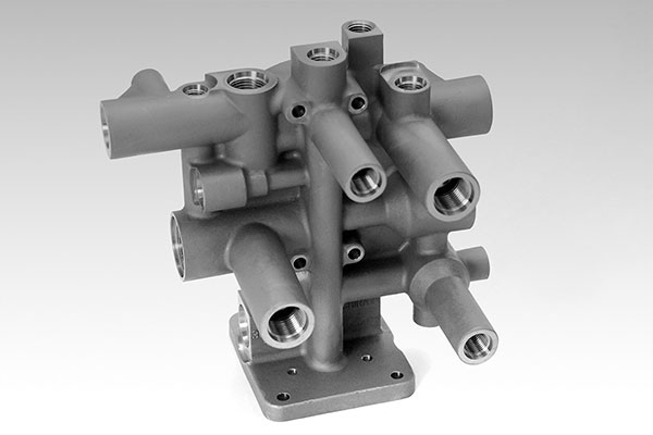
The optimization process underscores the importance of gating design in lost wax investment casting. By adjusting the number and arrangement of ingates, as well as insulation thickness, we can control the thermal gradient and solidification sequence. The V-shaped scheme, in particular, demonstrated robust performance by maintaining open feeding channels and promoting directional solidification. To visualize a typical application of lost wax investment casting in complex components, consider the following example of a manifold structure, which shares similarities with the support component in terms of geometry and casting challenges.
Validation through small-scale production confirmed the simulation findings. Using the V-shaped gating system, we conducted trials under identical process parameters. The resulting castings exhibited smooth surfaces without defects such as misruns or shrinkage cavities. X-ray inspections further verified the absence of internal porosity, meeting quality standards. This success highlights the efficacy of numerical simulation in replacing physical iterations for lost wax investment casting optimization.
In conclusion, the integration of ProCAST simulations into the lost wax investment casting process enables precise control over solidification and defect formation. Key factors include the fraction solid evolution, temperature gradient management, and application of the Niyama criterion. The V-shaped gating design proved optimal for the support component, ensuring bottom-up solidification and minimal defects. Future work could explore dynamic thermal parameters and advanced alloy systems to further enhance the lost wax investment casting process for high-integrity components.