According to the casting modulus theory, the larger the ratio of casting volume to surface area, the longer the solidification time, and the more severe the defect tendency of the casting. At the same time, the overall structure is a spatial irregular shape, with complex structures and multiple sharp angles. The resistance to alloy flow is high, especially in the U-shaped part, which is difficult to fill and prone to defects such as insufficient pouring and cold insulation.
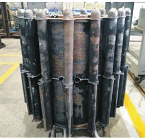
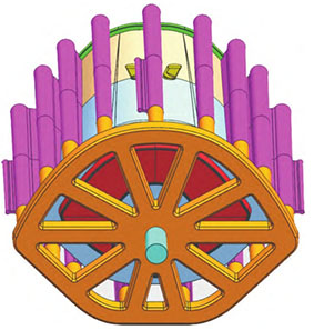
The cabin adopts sand mold low-pressure casting technology. The molten crucible is introduced into the sprue through the riser, and 10 sets of radioactive transverse runners are introduced into the sprue. The top of the transverse runners is connected by a circular transverse runner that follows the contour shape of the product. Above the circular transverse runner, 15 sets of vertical tubes and gap patch inner runners are connected. The gap of the inner runner is directly facing the longitudinal bars inside the cabin casting, effectively dispersing the heat before the sprue. The vertical gap sprue can ensure smooth and stable filling during casting, reduce casting defects, and achieve good internal quality. Due to the use of Mg-10Gd-0.5Y rare earth magnesium alloy in the casting, which has high viscosity and poor plasticity, high requirements for mold setback, and is prone to surface microcracks, clay sand technology is considered as the overall solution. The upper and lower frames are thicker and larger, and a circle of cold iron is set on each of the upper and lower surfaces. The metal liquid flow in the external Ω – shaped part is longer, making it difficult to supplement shrinkage. Cold iron is set on the Ω – shaped curved surface to adjust the local solidification sequence and reduce the probability of casting defects such as shrinkage and looseness.
Import the 3D model of the casting into ProCAST software for mesh division and boundary condition setting. The liquidus temperature of the alloy is 625 ℃, the solidus temperature is 580 ℃, and the density is 1.880 g/cm3; Adopting sand mold low-pressure casting, the sand mold material is clay sand, and the heat transfer coefficient between the casting and the sand mold is set to 300 W/(m2 · K). The flow field, temperature field, solidification field, and shrinkage porosity defect diagram of the casting filling process show that the filling of the molten metal is stable without obvious turbulence. The temperature of the molten metal increases in sequence from the U-shaped part, thin wall, upper and lower end frames, hidden riser, vertical tube, and transverse runner, which conforms to the ideal solidification order and is conducive to achieving shrinkage. The solidification rate decreases sequentially from the U-shaped part, thin wall, upper and lower end frames, hidden riser, riser, and runner, which conforms to the ideal layer by layer solidification sequence and is conducive to achieving shrinkage. The defects are mainly concentrated in the U-shaped part and Y-shaped mounting bracket, considering that the thickness of the cold iron in these two areas is relatively thin and does not fully meet the priority solidification conditions. The shrinkage at the intersection of the bottom runner is a normal situation, as this is a later solidification point.
(1) By using ProCAST software to simulate the temperature and solidification fields during the low-pressure casting process of a certain shaped cabin sand mold, the combination of low-pressure casting and vertical tube gap runner can ensure smooth and stable filling during casting, reducing the need for casting
Defects result in good internal quality of castings.
(2) The use of ProCAST software can predict the occurrence of shrinkage and porosity, optimize the casting process, and verify the effectiveness of simulation based on actual casting production.