
Enhancing the operational lifespan of the shell lining plates within the Φ10.37 m × 5.19 m large semi-autogenous (SAG) mill at the Dexing Copper Mine was critical for maintaining grinding efficiency. Initial service life was unacceptably short, primarily due to premature cracking and excessive wear. This necessitated a comprehensive optimization strategy encompassing the lining plate geometry, material composition, casting methodology, and heat treatment protocol.
1. Optimization of Lining Plate Structure
The initial shell lining plate arrangement comprised two rows of 44 plates each, totaling 88 plates. These plates were large (max length 2350 mm, weight > 2000 kg) with relatively thin backing plates. Under the severe impact loads characteristic of large SAG mills (large ore feed up to 250 mm and grinding balls > Φ120 mm), this design proved susceptible to cracking (Figure 2), leading to frequent failures.
Analysis using Discrete Element Method (EDEM) software provided crucial insights into the motion trajectory of ore and balls within the mill, revealing the influence of parameters like mill speed, number of lining plates, plate height, lifter face angle, and arrangement on power draw and material flow patterns. Based on these simulations, the lining plate structure and arrangement were radically redesigned:
- Increased Row Count & Reduced Plate Size: The arrangement was changed to three rows with 66 plates per row, totaling 198 plates. This significantly reduced the size and weight of individual plates.
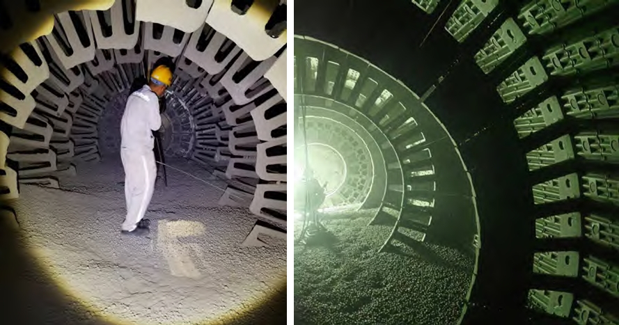
- Hi-Lo Configuration: Plates were arranged in a Hi-Lo pattern (Figure 5).
While this revision improved performance, achieving approximately 100 days of service life, plate fractures still occurred (Figure 6). Further structural refinement was implemented:
- Increased Lifter Dimensions: The height of the high lining plates was increased by 20 mm, and the working face thickness was augmented by 20 mm.
- Profiled Low Plates: The working surface of the low lining plates was redesigned into an arc shape (Figure 7).
This optimized lining plate geometry, combined with the Hi-Lo arrangement, successfully mitigated cracking issues and formed the foundation for achieving the target service life. The refined shape distributed impact stresses more effectively and improved material flow within the mill.
2. Material Selection and Chemical Composition
While high-manganese steel offers exceptional toughness, its relatively low yield strength makes it prone to deformation under the extreme impact conditions of large SAG mills. This deformation can lead to bolt breakage and difficult plate removal. Therefore, pearlitic Cr-Mo steels are the preferred material for large SAG mill shell lining plates globally.
Pearlitic steels provide a better balance of hardness and toughness for this application. However, achieving sufficient hardness often requires higher carbon content (typically 0.6% – 0.85%), which inherently increases the risk of brittle fracture, especially in large, thick-section castings like these lining plates. Balancing these factors was paramount.
Based on extensive research and analysis of field performance, the optimal carbon content range for the Φ10.37 m × 5.19 m SAG mill lining plates was determined to be 0.5% – 0.7%. To ensure adequate hardenability throughout the thick sections and achieve the necessary combination of hardness and impact toughness, alloying elements were carefully selected:
- Chromium (Cr): 2.0% – 3.5% to enhance hardenability, wear resistance, and tempering resistance.
- Molybdenum (Mo): Added in controlled amounts (typically 0.2% – 0.6%) to further improve hardenability (especially in thick sections), temper resistance, and high-temperature strength.
- Nickel (Ni) and Copper (Cu): Added in smaller quantities (typically Ni: 0.5% – 1.5%, Cu: 0.2% – 0.8%) primarily to enhance toughness, particularly at low temperatures, and contribute slightly to hardenability. Ni also helps mitigate any potential embrittlement effects.
The final nominal chemical composition range is summarized in Table 1.
| C | Si | Mn | Cr | Mo | Ni | Cu | P (max) | S (max) |
|---|---|---|---|---|---|---|---|---|
| 0.50 – 0.70 | 0.30 – 0.80 | 0.60 – 1.20 | 2.00 – 3.50 | 0.20 – 0.60 | 0.50 – 1.50 | 0.20 – 0.80 | 0.030 | 0.030 |
3. Optimization of Casting Process
The substantial weight and thick sections of large SAG mill lining plates make them prone to casting defects such as hot tears, sand burn-on/bonding, shrinkage porosity, and coarse grain structure. The initial casting design utilized multiple side gating with trapezoidal ingates (Figure 8). This approach proved problematic:
- Cracking at Ingates: Lining plates produced with this method frequently cracked near the ingate regions after only ~20 days of service (Figure 9). Dye penetrant inspection revealed that these cracks originated at the ingates.
- Cause: The large thermal mass at the ingate locations resulted in slower cooling rates. During solidification and subsequent cooling contraction, the constraint imposed by the mold at these hot spots generated significant thermal stresses, leading to hot tearing or cold cracking.
To eliminate this critical failure mode, the gating system was fundamentally redesigned (Figure 10):
- Top Gating via Runner: The pouring location was moved to the center of one end face of the lining plate.
- Single Circular Sprue/Runner: A single, circular cross-section sprue (using a ceramic tube) was implemented, effectively combining the runner and ingate functions.
- Benefits: This modification promoted directional solidification from the plate’s working face towards the feeder head located at the opposite end. It ensured better feeding to compensate for solidification shrinkage, minimizing the risk of shrinkage porosity and cavities. Crucially, it removed the thermal hotspots and associated stress concentrations inherent in the side-gating design.
Furthermore, strict control over the shakeout temperature was enforced:
- Delayed Shakeout: The molds were not opened until the lining plate surface temperature dropped below 300°C (typically requiring extended cooling times of 48-72 hours or more depending on mold design and ambient conditions).
- Purpose: This practice minimizes thermal gradients within the thick casting during cooling, significantly reducing residual casting stresses and the risk of stress-relief cracking. It allows for a more controlled and uniform cooling rate through the critical phase transformation ranges.
The governing equation for the solidification time ($t_s$) of a simple shape can be estimated using Chvorinov’s rule:
$$ t_s = B \left( \frac{V}{A} \right)^n $$
where:
- $t_s$ is the total solidification time,
- $B$ is the mold constant (incorporating metal and mold properties),
- $V$ is the volume of the casting,
- $A$ is the surface area of the casting through which heat is extracted,
- $n$ is an exponent, usually taken as 2 for sand castings.
For large, thick-section lining plates, both $V$ is large and the effective $A$ (especially considering insulating mold materials/sleeves on feeders) can be relatively small, leading to very long solidification and cooling times. The delayed shakeout protocol ensures the core of the casting has sufficiently cooled and transformed before the mold restraint is removed.
4. Heat Treatment Process
Heat treatment is essential for large, low-alloy steel lining plates to achieve the required microstructure and mechanical properties. The thick sections exacerbate tendencies like coarse as-cast grains and microsegregation. The demanding service conditions necessitate an optimal combination of high hardness for wear resistance and sufficient toughness to withstand impact loads without fracture.
A three-stage heat treatment cycle was developed and implemented: Annealing → Quenching → High-Temperature Tempering.
- Annealing:
- Purpose: To homogenize the microstructure (reducing chemical segregation from casting), dissolve brittle carbides formed during solidification, and most importantly, relieve internal casting stresses. This stress relief is critical to prevent cracking during the subsequent rapid heating or quenching stages.
- Typical Cycle: Heat slowly (to avoid thermal stress) to 840°C – 880°C, hold for sufficient time (typically 4-8 hours depending on plate thickness and furnace loading), followed by slow furnace cooling.
- Quenching:
- Purpose: To transform the austenitized microstructure into martensite, providing high hardness and strength.
- Process: Reheat the annealed lining plates to the austenitizing temperature (typically 830°C – 860°C for this composition). Hold for adequate time (ensuring complete austenitization and carbon dissolution – typically 1-3 hours). Quench rapidly in agitated oil or a polymer quenchant. Oil quenching provides a less severe quench than water, reducing the risk of distortion and quench cracking in such complex, heavy sections, while still achieving sufficient hardenability due to the alloy content (Cr, Mo, Ni). Polymer quenchants offer adjustable cooling rates between oil and water. The quenchant selection and agitation are critical for achieving uniform properties and minimizing distortion.
- High-Temperature Tempering:
- Purpose: To transform the brittle, as-quenched martensite into tempered martensite or, more specifically for this temperature range, a microstructure of tempered martensite with fine carbides, often described as a sorbitic structure (fine pearlite) or tempered troostite. This transformation drastically improves toughness and ductility while retaining a significant portion of the hardness and strength gained from quenching. It also further relieves residual stresses from quenching.
- Process: Reheat the quenched lining plates to a temperature typically between 500°C and 600°C (specific temperature depends on the desired hardness/toughness balance). Hold for sufficient time (usually 4-8 hours, rule of thumb 1 hour per inch of thickness minimum), followed by air cooling. Higher tempering temperatures result in lower hardness but higher toughness.
The resulting microstructure after this heat treatment sequence is predominantly tempered martensite (sorbitic structure) with fine, dispersed alloy carbides (Figure 11), providing the optimal blend of wear resistance and impact toughness.
The tempering process follows kinetic principles where the degree of softening and microstructural transformation depends on time and temperature. The Hollomon-Jaffe tempering parameter ($P$) is often used to correlate these effects for a given steel:
$$ P = T (C + \log_{10} t) $$
where:
- $P$ is the tempering parameter,
- $T$ is the absolute temperature (in Kelvin),
- $t$ is the tempering time (in hours),
- $C$ is a constant (approximately 20 for many low-alloy steels).
A higher $P$ value corresponds to a greater degree of tempering (softer condition).
The achieved mechanical properties consistently met the stringent requirements for large SAG mill lining plates (Table 2). The hardness range (35-42 HRC) provides excellent wear resistance, while the impact toughness values (60-80 J/cm²) ensure sufficient resistance to impact fracture under service loads.
| Property | Hardness (HRC) | Impact Toughness (J/cm²) | Tensile Strength (MPa) |
|---|---|---|---|
| Measured Values | 35 – 42 | 60 – 80 | 950 – 1100 |
| Target Values | > 35 | > 40 | – |
| National Standard (GB/T 26651)* | > 30 | > 25 | – |
*Reference to relevant national standard for wear-resistant cast steel for comparison.
5. Service Performance
The implementation of the optimized lining plate design, material composition, casting process, and heat treatment protocol yielded dramatic improvements in service life. The optimized lining plates were installed in the Φ10.37 m × 5.19 m SAG mill at the Dexing Copper Mine.
The average service life consistently exceeded 120 days, achieving the target of 4 months or more. Detailed wear measurements were conducted on plates after 125 days of operation. The results (Table 3) demonstrate a significant improvement over the initial performance. The average wear rate across the measured high and low lining plates was approximately 46%, indicating substantial remaining useful life even after 125 days.
| Lining Plate Type | Plate ID | Initial Weight (kg) | Weight After Service (kg) | Weight Loss (kg) | Wear Rate (%) |
|---|---|---|---|---|---|
| High Lining Plate | 1# | 815 | 490 | 325 | 40 |
| 3# | 860 | 390 | 470 | 55 | |
| 5# | 1410 | 770 | 640 | 45 | |
| Low Lining Plate | 2# | 450 | 250 | 200 | 44 |
| 4# | 476 | 240 | 236 | 50 | |
| 6# | 780 | 460 | 320 | 41 | |
| Total / Average | 4791 | 2600 | 2191 | 46 | |
This extended lining plate lifespan significantly reduced mill downtime for liner changes, improved operational efficiency, and lowered the total cost per ton of ore processed. The optimized lining plates demonstrated excellent resistance to both cracking and wear, validating the integrated optimization approach.
6. Conclusion
The premature failure of large SAG mill shell lining plates at the Dexing Copper Mine was successfully addressed through a systematic optimization of the entire production process. Key achievements include:
- Structural Optimization: Utilizing EDEM simulation insights, the lining plate geometry was redesigned (Hi-Lo pattern with increased lifter height/face thickness and profiled low plates) and the arrangement changed to three rows of smaller plates. This dramatically improved impact load distribution and material flow, eliminating catastrophic cracking.
- Material Optimization: A low-alloy Cr-Mo-Ni-Cu steel composition (0.5-0.7% C, 2.0-3.5% Cr) was selected and refined to provide the optimal balance of hardenability (for thick sections), hardness (35-42 HRC), and impact toughness (60-80 J/cm²).
- Casting Process Optimization: Replacing side gating with a single top-poured, circular sprue/runner system eliminated stress concentration points at ingates and promoted sound feeding. Strict control of shakeout temperature (< 300°C) minimized residual stresses.
- Heat Treatment Optimization: Implementing a robust Annealing → Quenching (Oil/Polymer) → High-Temperature Tempering cycle ensured a uniform, tempered martensitic microstructure (sorbitic structure), delivering the required combination of wear resistance and toughness throughout the heavy sections.
The synergistic effect of these optimizations resulted in lining plates consistently achieving service lives exceeding 120 days in the demanding Φ10.37 m × 5.19 m SAG mill environment. This represents a significant improvement over the initial performance and meets the operational targets for mill availability and cost-efficiency. The methodologies and results presented provide a valuable technical foundation and practical reference for the production and optimization of large SAG mill shell lining plates globally.