
In the realm of advanced manufacturing, prototype investment casting, often referred to as lost-wax casting, stands as a pivotal near-net-shape technology. It enables the production of intricate metal components with complex internal cavities, high melting temperatures, dimensional accuracy, minimal machining allowances, and low surface roughness. This process is extensively utilized in aerospace, automotive, and marine industries. However, prototype investment casting traditionally relies on extensive trial-and-error experiments, leading to prolonged production cycles and challenges in process control. With the trend toward larger, more complex, and thinner-walled castings, predicting and mitigating defects during filling and solidification has become a critical hurdle. The advent of numerical simulation technology offers a transformative tool for analyzing these processes, guiding practical production and optimizing prototype investment casting methodologies. In this work, we leverage MAGMA software to simulate and refine the prototype investment casting process for a bypass valve casting, demonstrating how simulation-driven design enhances efficiency and quality.
The core of prototype investment casting involves creating a wax pattern, building a ceramic shell around it, melting out the wax, and pouring molten metal into the cavity. Ensuring defect-free castings requires precise control over fluid flow and thermal dynamics. Numerical simulation allows us to virtually prototype the process, identifying potential issues like air entrainment, cold shuts, shrinkage porosity, and hot tears before physical trials. This not only reduces costs but also accelerates the development cycle for prototype investment casting projects.
Our focus is on a bypass valve casting, with overall dimensions of 120 mm × 132 mm × 253 mm, featuring a bent-pipe structure with wall thicknesses ranging from 10 to 25 mm. The material is 20Mn5M steel, weighing 6.7 kg. The casting demands high integrity, free from shrinkage, slag inclusions, and cracks. Initial analysis revealed isolated thermal junctions and long feeding distances in the “L”-shaped section, necessitating strategic gating design for effective feeding in this prototype investment casting setup.
To model the process, we first established the governing equations for fluid flow and heat transfer. The filling phase is described by the Navier-Stokes equations for incompressible flow, incorporating turbulence effects. The continuity and momentum equations are:
$$ \nabla \cdot \mathbf{v} = 0 $$
$$ \rho \left( \frac{\partial \mathbf{v}}{\partial t} + \mathbf{v} \cdot \nabla \mathbf{v} \right) = -\nabla p + \mu \nabla^2 \mathbf{v} + \rho \mathbf{g} + \mathbf{S} $$
where $\mathbf{v}$ is velocity, $\rho$ is density, $p$ is pressure, $\mu$ is dynamic viscosity, $\mathbf{g}$ is gravity, and $\mathbf{S}$ represents source terms such as momentum sinks due to solidification. For prototype investment casting, the mold is preheated, so energy conservation during filling and solidification is crucial. The heat transfer equation is:
$$ \rho c_p \frac{\partial T}{\partial t} = \nabla \cdot (k \nabla T) + Q_{\text{latent}} $$
where $T$ is temperature, $c_p$ is specific heat, $k$ is thermal conductivity, and $Q_{\text{latent}}$ is the latent heat release during phase change. The solidification model uses a fraction solid approach, where the fraction solid $f_s$ is defined as:
$$ f_s = \begin{cases}
0 & T > T_l \\
\frac{T_l – T}{T_l – T_s} & T_s \le T \le T_l \\
1 & T < T_s
\end{cases} $$
Here, $T_l$ and $T_s$ are the liquidus and solidus temperatures, respectively. For defect prediction, we employ criteria for shrinkage porosity based on the Niyama criterion, which relates thermal gradients and cooling rates:
$$ N_y = \frac{G}{\sqrt{\dot{T}}} $$
where $G$ is temperature gradient and $\dot{T}$ is cooling rate. Regions with $N_y$ below a threshold indicate susceptibility to microporosity in prototype investment casting.
We developed the initial gating system for the bypass valve prototype investment casting, as summarized in Table 1. The system included a pouring cup, runners, and multiple gates to feed different sections of the casting.
| Component | Dimensions (mm) | Purpose |
|---|---|---|
| Pouring Cup | Ø90 top, Ø50 bottom, height 90 | Metal entry |
| Runner | 30 × 60 × 255 | Distribute metal |
| Sprue 1# | 30 × 30 × 120 | Feed upper gates |
| Sprue 2# | 40 × 40 × 120 | Feed lower gates |
| Gate 1# | 15 × 25 × 20 | Feed side flange |
| Gate 2# | Ø60 × 20 (semi-cylindrical) | Main feed for body |
| Gate 3# | 11 thick × 15 high × 55 arc (×2) | Feed ring section |
| Gate 4# | 25 × 50 × 40 (conformal) | Feed outer ring wall |
Simulation parameters were set as per typical prototype investment casting conditions, detailed in Table 2. We used a mesh of approximately 5 million cells to ensure accuracy.
| Parameter | Value | Description |
|---|---|---|
| Casting Material | 20Mn5M Steel | Density: 7800 kg/m³, Thermal properties as per alloy data |
| Mold Material | Zircon Sand | Shell thickness: 7-8 mm, Preheat temperature: 950°C |
| Heat Transfer Coefficient | 500 W/(m²·K) | Interface between metal and shell |
| Pouring Temperature | 1560°C | Initial metal temperature |
| Pouring Speed | 3 kg/s | Gravity pouring simulation |
| Cooling Method | Air Cooling | Ambient temperature: 25°C |
| Simulation Software | MAGMA | Finite volume method for fluid flow and solidification |
The initial filling simulation revealed significant issues. At 10% fill, metal entered primarily through Gates 1#, 2#, and 4#, causing turbulent flow with velocities up to 1.5 m/s. Sprue 1# and Gate 3# received minimal flow, leading to discontinuous feeding and potential cold shuts. This turbulence risked air entrainment and oxide formation, common defects in prototype investment casting. The flow instability was attributed to the pouring cup location, which caused unbalanced metal distribution. To quantify flow behavior, we analyzed the Reynolds number $Re$ in critical regions:
$$ Re = \frac{\rho v L}{\mu} $$
where $L$ is characteristic length. In gates, $Re$ exceeded 4000, indicating turbulent flow that could exacerbate defect formation. The solidification simulation showed isolated liquid pools at thermal junctions, predicting shrinkage porosity. The fraction solid distribution at 64% solidification indicated liquid trapping in the “L”-section, with a Niyama value below 0.5 °C·s1/2/mm, confirming shrinkage risk.
Based on these findings, we optimized the prototype investment casting process. The key change was relocating the pouring cup directly above Gate 2# to ensure streamlined metal entry. This modification aimed to reduce turbulence and promote sequential filling. The optimized gating layout is summarized in Table 3, with adjustments to enhance feeding efficiency.
| Component | Modification | Rationale |
|---|---|---|
| Pouring Cup | Positioned above Gate 2# | Direct metal flow into main cavity, reduce turbulence |
| Gate 2# | Enlarged contact area | Improve feeding for body section |
| Gate 3# and 4# | Adjusted angles for better flow | Ensure continuous feeding to ring sections |
| Insulation | Added insulation wraps on runner and gates | Delay solidification, enhance feeding capacity |
Re-simulation of the optimized prototype investment casting process showed marked improvement. Filling became stable, with metal entering smoothly through Gate 2# at velocities around 1.8 m/s initially, decreasing to 0.6 m/s in lower sections. The flow was laminar in critical areas, reducing $Re$ to below 2000. The filling sequence ensured minimal air entrapment. Solidification analysis demonstrated sequential progression, with no isolated liquid zones. The fraction solid evolution followed a predictable pattern, as described by the solidification time $t_s$:
$$ t_s = \frac{\Delta H}{\rho c_p (T_p – T_s)} $$
where $\Delta H$ is latent heat and $T_p$ is pouring temperature. For the bypass valve, $t_s$ was calculated to be approximately 120 seconds in thick sections, allowing adequate feeding. Shrinkage prediction using the Niyama criterion indicated only minor risks in Gate 2# regions, with $N_y > 1.0$ °C·s1/2/mm in most casting areas, confirming soundness. The thermal gradient $G$ and cooling rate $\dot{T}$ were derived from simulation data, with average values of $G = 15$ °C/mm and $\dot{T} = 2.5$ °C/s in optimized zones.
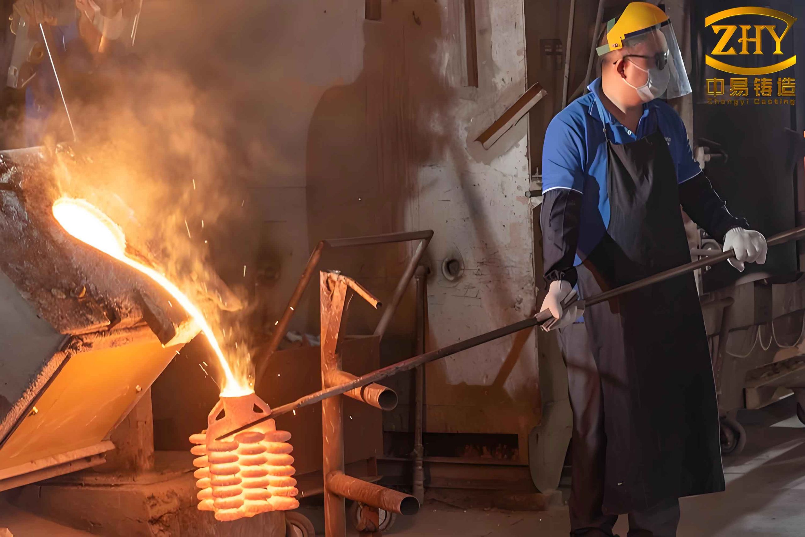
To validate the optimized prototype investment casting process, we proceeded with physical trials. The shell-making process employed a fully colloidal silica system, with parameters detailed in Table 4. Consistency in shell properties is vital for accurate simulation correlation in prototype investment casting.
| Layer | Slurry Material | Viscosity (Zahn 4# sec) | Stucco Material | Stucco Size (mesh) | Drying Time (h) |
|---|---|---|---|---|---|
| Primary 1-2 | Zircon flour-Silica sol | 42-48 | Zircon sand | 80-120 | 6-8 |
| Transition 3 | Chamotte flour-Silica sol | 21-27 | Chamotte sand | 30-60 | ≥10 |
| Backup 4-7 | Chamotte flour-Silica sol | 16-21 | Chamotte sand | 16-30 | ≥12 |
| Seal Coat | Chamotte flour-Silica sol | 10-15 | — | — | ≥24 |
The shells were fired at 950°C to remove wax and achieve thermal stability. Before pouring, insulation wraps (20 mm thick ceramic fiber) were applied to runners and gates as per simulation guidance, to modify solidification dynamics. This practical step aligns with the prototype investment casting optimization strategy. Pouring was conducted at 1560°C into preheated shells at 946°C, matching simulation inputs. The thermal history during cooling was monitored, and the temperature drop followed Newton’s law of cooling in later stages:
$$ T(t) = T_{\text{env}} + (T_0 – T_{\text{env}}) e^{-ht} $$
where $T_{\text{env}}$ is ambient temperature, $T_0$ is initial shell temperature, and $h$ is heat transfer coefficient. For our system, $h$ was estimated at 50 W/(m²·K) during air cooling.
Post-casting, the components were cleaned and inspected. Chemical composition of the 20Mn5M material was verified using spectrometry, with results meeting specifications as shown in Table 5. This consistency is essential for reliable prototype investment casting outcomes.
| Element | Required | Measured |
|---|---|---|
| C | ≤0.25 | 0.17 |
| Si | ≤0.60 | 0.56 |
| Mn | ≤1.20 | 1.03 |
| P | ≤0.020 | 0.016 |
| S | ≤0.020 | 0.004 |
Mechanical properties were evaluated on specimens subjected to normalization heat treatment: heating to 890°C at 80°C/h, holding for 2.5 hours, and air cooling. The results, presented in Table 6, exceed the required benchmarks, demonstrating the integrity achieved through optimized prototype investment casting.
| Test | Temperature | Property | Required Value | Measured Value |
|---|---|---|---|---|
| Tensile | Room Temperature | Yield Strength (Rp0.2, MPa) | ≥275 | 385 |
| Tensile Strength (Rm, MPa) | ≥485 | 559 | ||
| Elongation (A, %) | ≥20 | 31.5 | ||
| Reduction of Area (Z, %) | ≥35 | 54 | ||
| Tensile | 300°C | Yield Strength (Rp0.2, MPa) | ≥210 | 238 |
| Tensile Strength (Rm, MPa) | ≥435 | 524 | ||
| Impact | 0°C | Impact Energy (KV2, J) | ≥40 | 58.0, 67.1, 56.4 |
Non-destructive testing via X-ray inspection revealed no shrinkage porosity, cracks, or inclusions in all four trial castings. Additionally, sectioning of one casting confirmed the absence of macroscopic defects at critical junctions, validating the simulation predictions. The surface roughness was below 6.3 µm, satisfying the specification of ≤12.5 µm. These results underscore the efficacy of numerical simulation in refining prototype investment casting processes.
In conclusion, this study demonstrates the power of integrating numerical simulation into prototype investment casting development. By analyzing fluid flow and solidification through MAGMA software, we identified and mitigated potential defects in the bypass valve casting. The optimization involved repositioning the pouring cup and adding insulation, which stabilized filling and promoted sequential solidification. The simulated outcomes aligned closely with physical trials, yielding castings that met all chemical, mechanical, and quality standards. This approach reduces reliance on empirical trials, accelerates prototyping, and enhances cost-effectiveness in prototype investment casting. Future work could explore multi-objective optimization algorithms to further refine gating designs, or incorporate advanced materials models for alloys with complex solidification behavior. Ultimately, simulation-driven prototype investment casting paves the way for more robust and efficient manufacturing of intricate components across high-tech industries.
The success of this prototype investment casting project hinges on the detailed modeling of thermal and fluid dynamics. For instance, the heat flux $q$ across the metal-mold interface is critical, given by:
$$ q = h_c (T_m – T_s) $$
where $h_c$ is the interfacial heat transfer coefficient, $T_m$ is metal temperature, and $T_s$ is shell temperature. In our simulation, $h_c$ was set to 500 W/(m²·K), but actual values can vary; sensitivity analysis could refine this parameter for future prototype investment casting simulations. Moreover, the feeding efficiency during solidification can be quantified by the feeding pressure $P_f$:
$$ P_f = \rho g H – \Delta P_{\text{flow}} $$
where $H$ is metallostatic head and $\Delta P_{\text{flow}}$ is pressure loss in the gating system. Optimizing $P_f$ ensures adequate compensation for shrinkage in prototype investment casting. Additionally, the criterion for mistrun prevention involves ensuring the molten metal front temperature remains above the solidus temperature $T_s$ during filling. The temperature drop $\Delta T_{\text{fill}}$ can be estimated as:
$$ \Delta T_{\text{fill}} = \frac{h_a A (T – T_{\text{mold}})}{\rho c_p V} \Delta t $$
where $h_a$ is effective heat transfer coefficient during filling, $A$ is surface area, $V$ is volume, and $\Delta t$ is time step. By keeping $\Delta T_{\text{fill}} < T – T_s$, cold shuts are avoided in prototype investment casting.
Our experience confirms that prototype investment casting benefits immensely from virtual prototyping. The iterative simulation process allowed us to test multiple gating configurations rapidly, something impractical with physical trials. For example, we evaluated the effect of gate sizes on velocity profiles using the continuity equation $A_1 v_1 = A_2 v_2$ for incompressible flow, where $A$ is cross-sectional area and $v$ is velocity. Enlarging Gate 2# reduced velocity and turbulence, as predicted. Furthermore, the solidification time $t_s$ for different sections was computed to ensure feeding paths remain open, using the Chvorinov’s rule approximation:
$$ t_s = B \left( \frac{V}{A} \right)^n $$
where $B$ and $n$ are constants dependent on mold material and casting conditions. For zircon sand molds in prototype investment casting, $n \approx 2$. This helped design gates with favorable modulus ($V/A$) ratios.
In summary, the integration of numerical simulation into prototype investment casting workflows represents a paradigm shift. It enables precise control over complex processes, reduces material waste, and shortens lead times. As simulation tools evolve with better physical models and computing power, their role in prototype investment casting will expand, facilitating the production of even more sophisticated components. This case study of the bypass valve casting exemplifies how simulation-driven optimization can achieve high-quality outcomes in prototype investment casting, setting a benchmark for future endeavors in advanced manufacturing.