
In my role within a manufacturing engineering team, I was tasked with leading the process development for a large, complex driving wheel cast from ductile cast iron. This component is a vital part of a heavy-duty agricultural tractor’s undercarriage system. The successful production of this part presented significant challenges due to its intricate geometry, stringent quality requirements, and the inherent solidification characteristics of ductile cast iron. This narrative details the journey from initial design through simulation, iterative improvement, and final production, focusing on the methodologies employed to achieve a sound casting.
The driving wheel, with its external gear-like profile, is fabricated from a grade of ductile cast iron conforming to GGG60 per DIN 1693. The material specifications demand a combination of high strength and good ductility, which is characteristic of well-produced ductile cast iron. The key mechanical property requirements are summarized in the table below.
| Property | Symbol | Requirement |
|---|---|---|
| Tensile Strength | $$R_m$$ | ≥ 600 MPa |
| Yield Strength | $$R_{p0.2}$$ | ≥ 370 MPa |
| Elongation | $$A$$ | ≥ 3% |
| Brinell Hardness | HBW | 187 – 269 |
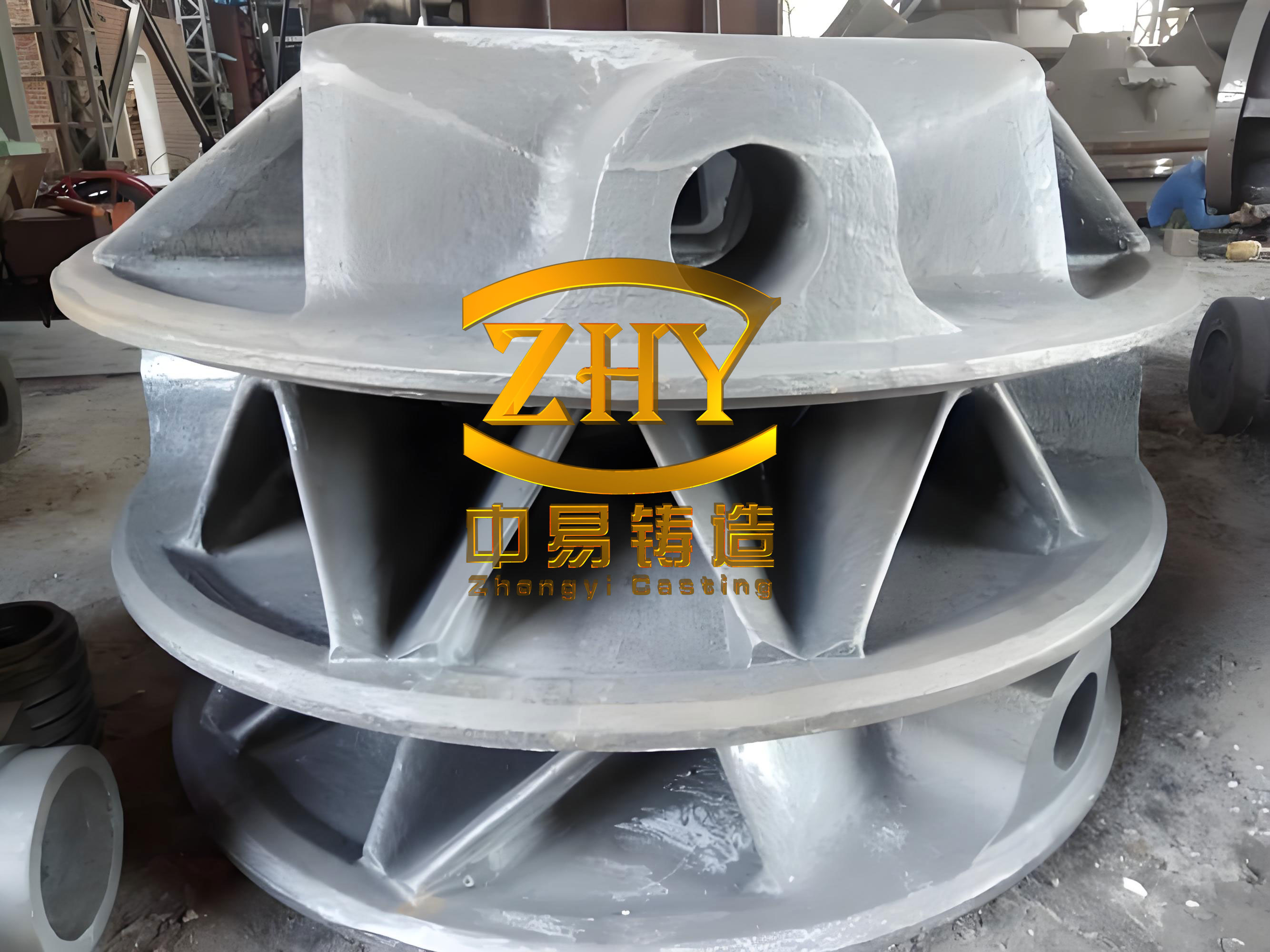
The casting’s dimensions are substantial: an outer diameter of 916 mm, a height of 526 mm, and a final weight of approximately 260 kg. Its most challenging feature is the presence of 19 equally spaced teeth around its circumference. Each tooth root forms an isolated thermal node, a classic site for shrinkage porosity in ductile cast iron castings. Furthermore, the functional design strictly prohibits any draft angle on the tooth flanks to ensure proper engagement with the tractor track. Quality standards were exceptionally high: internal soundness required Level 2 radiographic inspection, with dissection criteria allowing only isolated shrinkages smaller than ϕ12.7 mm within a 38.1 mm x 38.1 mm area. Surface finish criteria were equally strict, permitting no more than five gas holes (each ≤ 2 mm in diameter) in any equivalent area.
The first major task was devising a feasible molding strategy. Given the zero-draft requirement on the teeth, a conventional two-part mold with a straight pull was impossible. Our solution was a sophisticated core assembly system. The parting line was placed at the wheel’s axial mid-plane. Each of the 19 teeth was formed not by the mold itself, but by an assembled core cluster. We designed a system where individual tooth cores (designated 1# and 2#) were first bonded to form a tooth unit (3#). Three of these units were then precisely located and assembled within larger positioning cores (4# and 5#) to create a sector assembly (6#). Finally, six identical sector assemblies were placed into the drag (bottom mold). This approach minimized flash at the critical tooth profiles and allowed for excellent dimensional control of these features. The main mold halves were produced using furan resin sand for strength, while the intricate 1#, 2#, 4#, and 5# cores were made using a hot-box coated sand process for superior accuracy and surface finish.
With a preliminary process layout in hand, we employed computational modeling to predict the casting’s solidification behavior and identify potential defects before any metal was poured. We used ProCAST, a finite-element-based simulation software, to analyze the thermal and fluid dynamics during solidification of the ductile cast iron. The initial simulation, using a simple center-gating system, revealed a significant problem. Pronounced shrinkage porosity was predicted at the center of each tooth, exactly at the isolated hot spots we had identified. The predicted defect volume exceeded the strict acceptance criteria. This result confirmed that the natural solidification pattern of the ductile cast iron was insufficient to feed these thick sections.
The simulation became our primary tool for iterative improvement. We systematically tested modifications to the feeding system. The key insight was that applying a feeding source (a riser) directly above each tooth had a dramatic effect. The simulation showed that a properly sized riser could effectively transfer liquid ductile cast iron to compensate for the solidification shrinkage in the tooth below. However, the riser’s influence was limited by distance. To extend this effective feeding range and further reduce the thermal mass of the tooth root, we introduced chills at the base of each tooth. Chills, typically made of iron or copper, act as heat sinks, accelerating solidification and directing the solidification front toward the riser. The modified simulation showed the shrinkage defect migrating from the tooth’s center toward its upper region and significantly diminishing in size.
This led to the detailed engineering of the feeding system. The design was based on modulus calculations, a fundamental principle in feeding ductile cast iron castings. The modulus $$M$$ is defined as the casting volume $$V$$ divided by its cooling surface area $$A$$:
$$ M = \frac{V}{A} $$
For an individual tooth, with a mass $$G_c = 4.44 \text{ kg}$$, volume $$V_c \approx 0.000603 \text{ m}^3$$ (6030 cm³), and surface area $$A_c \approx 0.0558 \text{ m}^2$$ (558 cm²), the modulus was calculated as:
$$ M_c = \frac{V_c}{A_c} \approx 0.0108 \text{ m} = 1.08 \text{ cm} $$
We opted for a controlled pressure riser design. The mass feeding demand quotient $$Q_m$$ was calculated as:
$$ Q_m = \frac{G_c}{M_c^3} = \frac{4.44}{1.08^3} \approx 3.52 \text{ kg/cm}^3 $$
Using empirical factors ($$f_1$$, $$f_2$$, $$f_3$$) derived from charts correlating $$M_c$$ and $$Q_m$$ for ductile cast iron, the required riser body modulus $$M_R$$ was determined:
$$ M_R = f_1 \cdot f_2 \cdot f_3 \cdot M_c = 1.19 \times 0.76 \times 1.2 \times 1.08 \approx 1.17 \text{ cm} $$
The riser neck modulus $$M_N$$, critical for ensuring timely feed metal flow before freeze-off, was calculated with additional factors ($$f_p$$, $$f_4$$):
$$ M_N = f_p \cdot f_4 \cdot M_R = 0.65 \times 0.9 \times 1.17 \approx 0.68 \text{ cm} $$
This neck modulus corresponds to a neck diameter of approximately 52 mm. For a cylindrical blind riser with a height-to-diameter ratio $$K = H/D = 1.8$$, a standard riser with dimensions ϕ80 mm x 120 mm was selected. The final gating system was redesigned as a runner connecting all 19 risers, with ingates linking each riser to its corresponding tooth. The pouring temperature for the ductile cast iron was set between 1355°C and 1365°C.
| Parameter | Symbol | Value | Unit |
|---|---|---|---|
| Tooth Mass | $$G_c$$ | 4.44 | kg |
| Tooth Modulus | $$M_c$$ | 1.08 | cm |
| Mass Quotient | $$Q_m$$ | 3.52 | kg/cm³ |
| Riser Modulus | $$M_R$$ | 1.17 | cm |
| Riser Neck Modulus | $$M_N$$ | 0.68 | cm |
| Selected Riser Size | H x D | 120 x 80 | mm |
Prototype castings were produced using this revised riser-and-chill design. Sectioning and macro-examination of the teeth confirmed the simulation’s prediction: the major shrinkage cavities at the tooth centers were eliminated. Only minor, acceptable micro-porosity was occasionally found in the upper regions near the riser necks, well within specification limits. This was a major victory for the internal soundness of the ductile cast iron component. However, a new and severe issue emerged: the casting surfaces, particularly in the cored areas, exhibited extensive gas hole defects, rendering the parts commercially unacceptable despite their internal integrity.
A thorough investigation into the surface gas defect was initiated. The root cause was attributed to the high gas generation from the numerous complex resin-bonded sand cores during the pouring and initial solidification of the ductile cast iron. The relatively thin sections of the wheel geometry did not allow for sufficient venting of this large volume of gas. To mitigate this, a multi-pronged approach was implemented. First, the core sand mix was modified; the finer sand originally used for the 1# and 2# tooth cores was replaced with a coarser 50/100 mesh sand. The larger grain size reduces the specific surface area and the total amount of resin binder per unit volume, thereby lowering the core’s potential gas generation. The relationship between grain size and specific surface area can be approximated, though the primary goal was practical gas reduction.
Second, and most critically, we introduced a core drying process. After the complex 6# sector cores were fully assembled, they were placed in a convection oven. The thermal cycle was designed to cure any residual binder and, more importantly, to proactively drive off low-temperature volatiles before the core was exposed to molten ductile cast iron. The drying parameters were set at a holding temperature of 180°C for a duration of 4 hours. This process significantly reduced the instantaneous gas pressure within the mold cavity during pour. Third, the mold and core assembly were redesigned to incorporate explicit venting channels, allowing gases a direct escape path to the atmosphere rather than being forced into the solidifying ductile cast iron.
The effectiveness of these combined measures was proven in production. Over 120 driving wheels were subsequently cast. The incidence of surface gas holes was reduced to virtually zero, with all castings meeting the stringent surface quality standards. The success hinged on addressing the unique behavior of the ductile cast iron during solidification and its interaction with the mold materials.
To generalize the learnings from this project, we can formalize some of the governing principles. The solidification time $$t_s$$ for a casting section, crucial for riser design, is often expressed using Chvorinov’s rule:
$$ t_s = B \cdot \left( \frac{V}{A} \right)^n = B \cdot M^n $$
where $$B$$ is a mold constant and the exponent $$n$$ is typically around 2 for many sand cast conditions. For a riser to effectively feed a casting section of modulus $$M_c$$, its modulus $$M_R$$ must be greater, and the feeding channel (neck) must remain open longer. The design sequence we followed ensures this. Furthermore, the need for chilling arises from the desire to control the solidification gradient. The chilling power can be related to the heat diffusivity $$b$$ of the chill material, where $$b = \sqrt{k \rho c_p}$$, with $$k$$ being thermal conductivity, $$\rho$$ density, and $$c_p$$ specific heat. Iron chills, with high $$b$$ values, rapidly extract heat, modifying the local solidification time $$t_{s,chill}$$:
$$ t_{s,chill} \propto \frac{1}{b^2} $$
This creates a directional solidification pattern toward the riser. The gas generation problem underscores another critical area: mold-metal interaction. The volume of gas $$V_g$$ produced by a decomposing sand core can be estimated based on the binder content and its decomposition chemistry. Minimizing this volume or providing adequate venting area $$A_v$$ is essential to prevent gas entrapment in the ductile cast iron. A simple rule of thumb is to ensure venting capacity exceeds gas generation rate.
| Process Stage | Initial Approach | Improved Approach | Primary Impact on Ductile Iron Casting |
|---|---|---|---|
| Molding | Conventional two-part mold (impossible due to zero draft). | Complex core assembly system using specialized core sands. | Enabled production of zero-draft teeth with minimal flash. |
| Feeding System | Central gating with no dedicated feeding for teeth. | Individual riser (ϕ80×120 mm) per tooth, with iron chills at tooth base. | Eliminated major shrinkage porosity in isolated hot spots of the ductile iron. |
| Core Making | Standard coated sand for all cores. | Coarser sand for critical cores + Post-assembly baking (180°C, 4h). | Drastically reduced gas generation, eliminating surface blowholes. |
| Venting | Reliance on natural sand permeability. | Added explicit vent channels in core assemblies and mold. | Provided positive escape path for decomposed gases away from the solidifying ductile cast iron. |
In conclusion, the successful production of this high-integrity ductile cast iron driving wheel was a result of systematically addressing multiple interconnected challenges. The core assembly strategy solved the geometric constraint. Numerical simulation guided the effective design of a distributed feeding system using risers and chills to manage the solidification shrinkage characteristic of ductile cast iron. Finally, recognizing and mitigating mold gas generation through core material selection and a dedicated baking process was essential to achieve the required surface quality. This project underscores that modern casting of complex components in ductile cast iron is an engineering discipline reliant on both foundational principles—like modulus calculations and directional solidification—and advanced tools like simulation software, all applied through a rigorous, problem-solving methodology. The consistent focus on the specific solidification and feeding behaviors of ductile cast iron was the common thread that tied all successful improvements together.