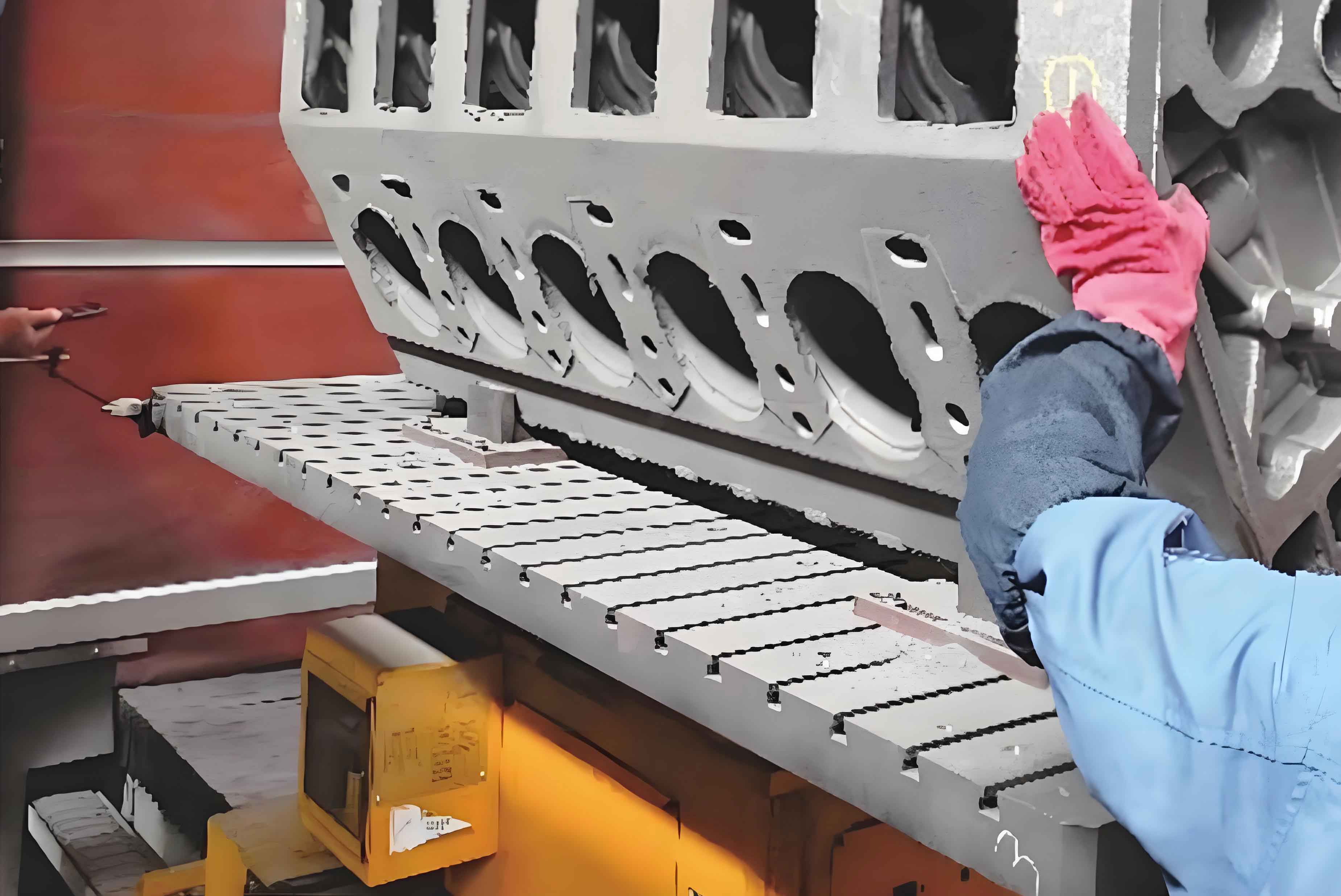
As a manufacturing engineer specializing in automotive components, I have dedicated significant efforts to refining the machining processes for engine cylinder blocks, particularly focusing on the precision and efficiency of cylinder bore fabrication. The engine cylinder block serves as the backbone of internal combustion engines, and its cylinder bores demand exceptional dimensional accuracy, surface finish, and structural integrity. This article synthesizes years of hands-on experience, technical analyses, and process optimizations to address common challenges in cylinder bore machining while emphasizing the critical role of parameter control, tooling innovations, and equipment modifications.

1. Fundamental Machining Processes for Engine Cylinder Blocks
The engine cylinder block undergoes a series of machining operations to achieve its final geometry and functional requirements. Key processes include milling, drilling, grinding, and turning, each contributing to the dimensional stability of the cylinder bores.
1.1 Milling
Milling operations are primarily employed for creating planar surfaces, edges, and grooves on the engine cylinder block. Tool thickness and feed rate must be optimized to prevent excessive material removal, which could compromise structural rigidity. For instance, the relationship between tool wear (WW) and material removal rate (MRRMRR) can be expressed as:W=k⋅MRRnW=k⋅MRRn
where kk and nn are material-specific constants.
Table 1: Typical Milling Parameters for Engine Cylinder Blocks
| Material | Tool Diameter (mm) | Spindle Speed (RPM) | Feed Rate (mm/min) |
|---|---|---|---|
| Cast Iron | 50–80 | 800–1200 | 200–400 |
| Aluminum | 40–60 | 1500–2000 | 400–600 |
1.2 Drilling
Drilling is critical for creating pilot holes, coolant passages, and valve seats. Aluminum engine cylinder blocks pose unique challenges due to their low hardness, leading to chip adhesion and burr formation. The thrust force (FF) during drilling can be modeled as:F=C⋅f0.8⋅d1.2F=C⋅f0.8⋅d1.2
where CC is a constant, ff is the feed rate, and dd is the drill diameter.
1.3 Grinding
Grinding ensures the required surface roughness (Ra≤0.2 μmRa≤0.2μm) for cylinder bores. The selection of grinding wheels and control of grinding trajectories are paramount. Surface roughness (RaRa) correlates with grinding wheel grit size (GG) and depth of cut (apap):Ra=0.25⋅G−0.7⋅ap0.3Ra=0.25⋅G−0.7⋅ap0.3
1.4 Turning
Turning operations demand high machine rigidity to minimize vibrations, which could degrade bore roundness. Cutting speed (VcVc) and tool geometry significantly influence surface finish:Vc=π⋅D⋅N1000Vc=1000π⋅D⋅N
where DD is the bore diameter and NN is the spindle speed.
2. Challenges in Cylinder Bore Machining
The engine cylinder block’s asymmetric wall thickness and varying bore diameters (7–9 mm) introduce complexities such as clamping deformation, thermal expansion, and tool wear. Common issues include:
2.1 Thrust Surface Wear
Thrust surfaces (130 mm diameter, 3.09 MPa pressure) experience accelerated wear due to high contact stresses. Redesigning thrust surfaces to 136 mm diameter and reducing pressure to 2.3 MPa mitigated this issue.
2.2 Residual Burrs on Main Shaft Holes
Post-machining burrs at gear positions lead to assembly failures. Implementing a 0.5 mm × 45° chamfering tool eliminated burrs by redistributing cutting forces.
2.3 Dimensional Inaccuracy
Variations in bore diameter (±0.02 mm) and cylindricity (±0.01 mm) necessitate stringent process controls. The relationship between machining error (ΔΔ) and clamping force (FcFc) is:Δ=α⋅Fc1.5Δ=α⋅Fc1.5
where αα is a deformation coefficient.
3. Optimization Strategies for Cylinder Bore Machining
3.1 Machine Tool Modifications
- Slider and Ram Adjustments: Increasing slider travel by 3 mm and ram stroke by 6 mm accommodated larger thrust surfaces.
- U-Axis Retrofitting: Shortening the U-axis limit by 6 mm enhanced stroke capacity for oversized bores.
Table 2: Machine Retrofit Parameters
| Component | Original Value | Modified Value |
|---|---|---|
| Slider Travel | 14.9 mm | 17.9 mm |
| Ram Stroke | 6 mm | 12 mm |
| U-Axis Limit | 19.3 mm | 13.3 mm |
3.2 Tooling Innovations
- Chamfering Tools: Eccentric entry tools with dual cutting edges reduced burr formation.
- Wear-Resistant Coatings: TiAlN-coated tools extended tool life by 40% in aluminum machining.
3.3 Fixture Design
Custom fixtures minimized clamping deformation. For example, sleeve-type fixtures improved concentricity by 30% during semi-finishing.
3.4 Process Parameter Optimization
Adjusted cutting parameters for roughing, semi-finishing, and finishing stages:
Table 3: Cutting Parameters for Bore Machining
| Stage | Tool Type | Cutting Speed (m/min) | Feed Rate (mm/rev) | Depth of Cut (mm) |
|---|---|---|---|---|
| Roughing | Carbide Insert | 120–150 | 0.15–0.25 | 1.5–2.0 |
| Semi-Finishing | CBN Tool | 200–250 | 0.08–0.12 | 0.5–1.0 |
| Finishing | Diamond Grinder | 300–400 | 0.03–0.05 | 0.05–0.1 |
4. Mathematical Models for Precision Control
4.1 Surface Roughness Prediction
A multi-variable regression model for surface roughness (RaRa) incorporates spindle speed (NN), feed rate (ff), and depth of cut (apap):Ra=0.12⋅N−0.4⋅f0.6⋅ap0.3Ra=0.12⋅N−0.4⋅f0.6⋅ap0.3
4.2 Tool Life Estimation
Tool life (TT) in minutes for carbide tools machining cast iron is given by:T=3000Vc1.2⋅f0.5⋅ap0.8T=Vc1.2⋅f0.5⋅ap0.83000
4.3 Thermal Deformation Compensation
Thermal expansion (δδ) during machining can be offset using:δ=β⋅ΔT⋅Lδ=β⋅ΔT⋅L
where ββ is the thermal expansion coefficient, ΔTΔT is temperature rise, and LL is bore length.
5. Case Study: Improving Bore Roundness
For an engine cylinder block with a nominal bore diameter of 85 mm, implementing the following measures improved roundness from ±0.015 mm to ±0.006 mm:
- Fixture Stiffness Enhancement: Increased clamping rigidity reduced deformation by 25%.
- Tool Path Optimization: Helical interpolation minimized tool deflection.
- Coolant Strategy: High-pressure coolant (70 bar) reduced cutting temperatures by 15%.
6. Conclusion
Optimizing the machining processes for engine cylinder block cylinder bores requires a holistic approach encompassing machine retrofits, tooling advancements, and data-driven parameter adjustments. By addressing thrust surface wear, burr formation, and dimensional inaccuracies through systematic modifications, manufacturers can achieve bore accuracies within ±0.005 mm±0.005mm and surface finishes below Ra=0.2 μmRa=0.2μm. Future work will focus on integrating real-time monitoring systems to further enhance process stability and repeatability for high-volume production of engine cylinder blocks.
