
The relentless pursuit of high-integrity, structurally sound castings has driven the development of various advanced foundry techniques. Among these, Vacuum Die Casting (VDC) stands out as a critical method for significantly reducing one of the most persistent and detrimental defects in metal casting: porosity in casting. The presence of gas pores, whether entrapped during filling or formed during solidification, severely compromises mechanical properties, pressure tightness, and surface finish. While the principle of evacuating air from the die cavity before metal injection is conceptually straightforward, its successful implementation hinges on precise process control. A paramount, yet often nuanced, parameter is the precise timing for terminating the vacuum draw, known as the Vacuum Dead-point or cut-off point. This article, drawn from extensive industrial experience and analysis, delves into a systematic exploration of how the strategic positioning of this vacuum cut-off point fundamentally influences cavity evacuation efficiency and, consequently, the degree of porosity in casting.
1. The Adversary: Understanding Porosity in Casting
Porosity in casting primarily manifests in two forms: gas porosity and shrinkage porosity. In high-pressure die casting, gas porosity is predominant, caused by the entrapment of air (and gases from lubricant burn-off) within the die cavity. As the molten metal front advances at high velocity, it can trap pockets of air, leading to voids upon solidification. The detrimental effects are quantifiable: a reduction in tensile strength, fatigue life, and an increased propensity for leakage in pressure-critical applications. The primary objective of Vacuum Die Casting is to mitigate this by creating a sub-atmospheric pressure environment within the cavity, thereby minimizing the volume of gas available for entrapment. The effectiveness of this evacuation is not merely a function of the ultimate vacuum level achieved but is profoundly sensitive to the sequence and timing of the vacuum valve operation relative to the plunger movement.
2. System Architecture and Process Cycle of Vacuum Die Casting
A typical industrial VDC system consists of several integrated components. Understanding this setup is crucial for contextualizing the vacuum cut-off point.
| System Component | Primary Function |
|---|---|
| Control Cabinet | Houses the programmable logic controller (PLC) for sequencing and activating the vacuum valve based on plunger position signals. |
| Vacuum Tank (Receiver) | A large reservoir maintained at a high vacuum level (e.g., ≤ -0.08 MPa gauge), providing the pressure differential needed for rapid cavity evacuation. |
| Vacuum Valve | A fast-acting, mechanically or hydraulically actuated valve mounted directly on the die. It forms the critical interface between the die cavity and the vacuum tank. |
| Position Sensors/Limit Switches | Mounted on the shot sleeve or plunger rod, they provide real-time positional feedback to the PLC to trigger the “VACUUM ON” and “VACUUM OFF” commands. |
The synchronized process cycle for a vacuum-assisted shot follows this strict sequence:
- Die Closure and Clamping.
- Slow Shot Phase: The plunger advances at low speed to fill the shot sleeve without turbulence.
- Vacuum Valve Opens: Triggered at a preset plunger position, connecting the cavity to the vacuum tank.
- Vacuum Valve Closes (Dead-point): Triggered at another critical plunger position, isolating the cavity.
- Fast Shot Phase: The plunger accelerates to high speed, forcing metal into the cavity.
- Intensification Phase: Additional pressure is applied to feed solidification shrinkage.
- Dwell/Pressure Holding.
- Die Opening and Casting Ejection.
The temporal window between steps 3 and 4 is the active evacuation period. Its termination point (step 4) is the focal variable for optimizing the reduction of porosity in casting.
3. The Mechanics of Evacuation and the Criticality of the Cut-Off Point
The vacuum valve operates as a three-state device. In its default position, the flow path between the die cavity and the vacuum tank is sealed. Upon receiving the “ON” signal, an actuator shifts an internal piston, opening a large-diameter port that creates a direct conduit for air to be extracted from the cavity into the pre-evacuated tank. When the “OFF” signal (Dead-point command) is received, the piston returns, sealing the port once more.
The rationale for an optimally timed cut-off is twofold, governed by fluid dynamics and practical production concerns:
a) Theoretical Foundation: The goal is to evacuate the maximum volume of air while preventing the premature ingress of molten metal into the vacuum system. The gas flow during evacuation can be modeled simplistically using the ideal gas law under isothermal conditions for the air in the cavity (volume $V_c$) and the tank (volume $V_t$). Before evacuation, the cavity pressure is atmospheric ($P_{atm}$). After the valve opens and the system reaches equilibrium, the combined pressure $P_f$ is given by:
$$ P_f (V_c + V_t) = P_{atm} V_c + P_{t,initial} V_t $$
where $P_{t,initial}$ is the initial tank vacuum (e.g., -0.095 MPa abs). The final cavity pressure before metal injection is approximately $P_f$. To maximize reduction in porosity in casting, we need to minimize $P_f$. This requires the valve to be open for a sufficient duration for pressure equilibration. However, if the valve remains open too long, as the slow-shot metal front approaches the ingates, the pressure differential ($\Delta P = P_{atm} – P_f$) across the molten metal can cause it to be “sucked” or drawn prematurely into the cavity.
This premature flow, akin to a gravity pour, is problematic. It leads to:
- Metal Dripping & Ingate Blockage: The slow, dripping flow can solidify partially in the ingate, creating a flow obstruction. This increases resistance during the subsequent fast shot, causing defects like mist runs or cold shuts, and ironically, can increase turbulence and gas entrapment—counteracting the goal of reducing porosity in casting.
- Contamination of Vacuum System: If the valve is still open when the fast shot begins, high-velocity metal can penetrate into the valve mechanism and even the vacuum tank, causing severe damage and requiring extensive downtime for cleaning.
b) The Optimization Problem: Therefore, the Vacuum Dead-point must be set late enough to allow for near-complete pressure equalization (minimizing $P_f$), but early enough to prevent any molten metal from being pulled into the cavity or reaching the valve port before the fast shot commences. Empirical and simulation studies consistently point to an optimal window.
4. Experimental Investigation: Quantifying the Impact on Casting Integrity
To systematically quantify the effect of the Vacuum Dead-point position, a controlled study was conducted using a production component—a pneumatic tool handle. The setup utilized a 5000 kN cold-chamber die casting machine.
| Process Parameter | Value / Setting |
|---|---|
| Slow Shot Speed | 0.27 m/s |
| Fast Shot Speed | 2.1 m/s |
| Intensification Pressure | 24 MPa |
| Metal Temperature (Aluminum Alloy) | 640 °C |
| Shot Weight (per cycle, 2 cavities) | 1.6 kg |
| Vacuum Tank Baseline Pressure | ≤ -0.06 MPa (gauge) |
The key variable was the position of the vacuum valve closure relative to the trigger point for the fast shot (defined as position ‘0 mm’, corresponding to the plunger location where the metal melt reaches the ingates). The Dead-point was tested at 15 distinct positions, ranging from -135 mm (i.e., 135 mm before the fast shot) to +10 mm (10 mm after the fast shot start). For each setting, multiple castings were produced and their masses were precisely measured. In a process where other parameters are held constant, an increase in part mass directly correlates with a decrease in volumetric porosity in casting, as voids are replaced by denser metal.
The data was compelling. When the vacuum was cut off very early (e.g., at -135 mm or -115 mm), the casting mass was lower. This indicated that air re-infiltration into the cavity occurred during the prolonged interval between valve closure and metal injection, negating much of the benefit of the initial evacuation. The plot of casting mass versus Dead-point position revealed a clear asymptotic curve. The mass increased steadily as the cut-off point was moved closer to the fast shot point, maximizing in the region just before the ‘0 mm’ position.
To normalize the data, a relative density ratio was calculated, referencing the mass at the -15 mm position as a baseline (100%). The results are summarized below:
| Vacuum Dead-point Relative to Fast Shot (mm) | Trend in Casting Mass | Interpretation & Effect on Porosity |
|---|---|---|
| -135 to -75 | Low, increasing gradually | Early cut-off allows significant air re-entry. Limited reduction in porosity in casting. |
| -50 to -25 | Steady, significant increase | Evacuation is more effective with less time for air re-infiltration. Porosity in casting is notably reduced. |
| -20 to -10 | Peak, plateau region | Optimal Window. Maximum cavity evacuation achieved just before metal enters. Minimal air re-entry and no metal ingress into valve. Minimum porosity in casting. |
| 0 to +10 | Potential decrease or instability | Risk zone. Valve closure is too late, risking metal dribble and valve contamination. Process becomes unreliable. |
The mass increase observed in the optimal window (-20 mm to -10 mm) corresponded to a density increase exceeding 1% compared to the very early cut-off scenarios. This density gain is not trivial; it can be conceptually equated to the elimination of a spherical gas pore with a diameter of approximately 14.5 mm from the casting’s volume. Microstructural analysis of sections from castings produced with the Dead-point set at -15 mm confirmed a dramatic reduction in visible gas pores compared to non-vacuum or poorly-timed vacuum cycles.
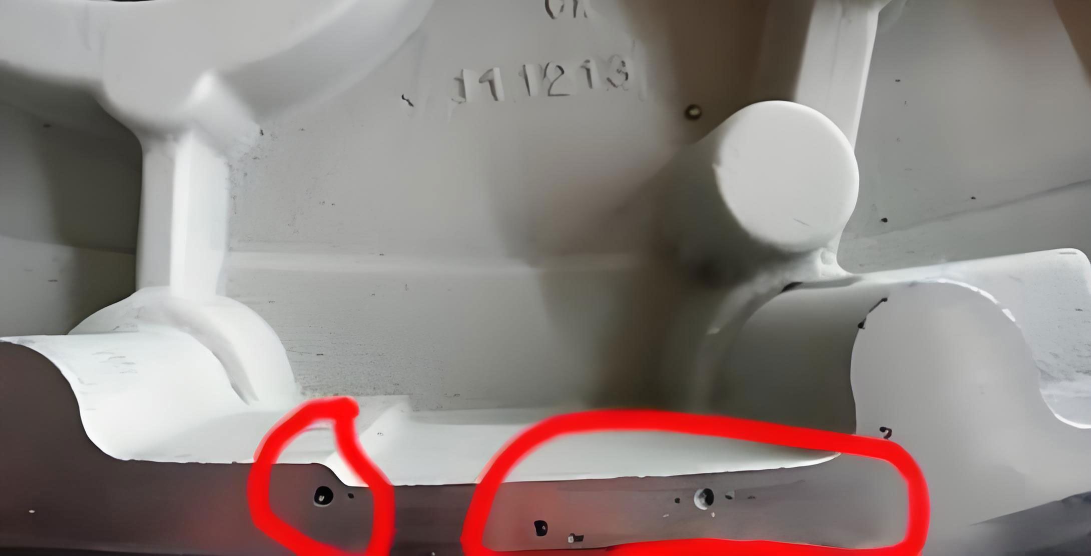
The image above illustrates the typical morphology of porosity in casting, a defect that the optimized vacuum process seeks to eliminate. The improved microstructure directly translates to enhanced mechanical performance. The yield and tensile strength of components can show marked improvement, while the scrap rate due to leaking parts can be drastically reduced.
5. Integrated Process Optimization: Beyond the Dead-point
While the Vacuum Dead-point is a linchpin parameter, it does not operate in isolation. Its optimization must be integrated with other key factors to achieve the lowest possible porosity in casting:
a) Vacuum Tank Capacity and Pumping Speed: The system must be capable of drawing down the cavity pressure rapidly. A larger tank volume ($V_t$) or a higher pumping speed improves the pressure ratio $\Lambda = \frac{V_t}{V_c}$, leading to a lower $P_f$ according to the gas law equation. The system should maintain a tank vacuum of at least -0.08 MPa (gauge) prior to each shot.
b) Die Sealing: The efficiency of vacuum die casting is utterly dependent on the ability to seal the die parting line, ejector pins, and core slides. Any leak paths allow air to be drawn back into the cavity after the vacuum valve closes, increasing the effective $P_f$. High-quality sealants and well-maintained die components are essential.
c) Shot Profile Synchronization: The kinetics of the plunger must be perfectly synchronized with the vacuum valve commands. The fast shot must be triggered immediately after the valve closes at the optimal Dead-point. Any delay introduces a window for pressure recovery. The plunger velocity during the slow shot must also be controlled to prevent “over-running” the vacuum draw and causing premature metal movement.
d) Metal Quality and Biscuit Design: The molten metal itself should be degassed to minimize hydrogen content, addressing another source of gas porosity. Furthermore, the design of the biscuit (the leftover metal in the shot sleeve) must ensure a complete seal behind the plunger during the shot to prevent air from being pumped into the cavity from the sleeve.
6. Conclusion and Forward Outlook
The strategic placement of the vacuum cut-off point, or Dead-point, is a decisive factor in harnessing the full potential of Vacuum Die Casting to combat porosity in casting. Based on systematic experimental data and process mechanics, terminating the vacuum draw when the plunger is 15 to 20 mm before triggering the high-speed injection phase consistently yields the optimal outcome. This timing maximizes air evacuation from the cavity while preventing the detrimental effects of premature metal flow and system contamination. The result is a quantifiable increase in casting density, often exceeding 1%, which corresponds to a substantial improvement in structural integrity and functional performance.
Mastering this parameter is a critical step towards producing high-performance, lightweight, and reliable castings for demanding applications in the automotive, aerospace, and consumer electronics industries. As simulation tools become more sophisticated, they will allow for even finer prediction and optimization of the evacuation dynamics, including the precise Dead-point, for each unique die geometry. The continuous refinement of this parameter, alongside advancements in die sealing technology and real-time process control, will remain at the forefront of efforts to eradicate porosity in casting and push the boundaries of what is possible with die-cast components.