
Abstract: This article delves into the development of a comprehensive automation cleaning process for high-end heavy-duty engine cylinder block casting. It addresses the challenges faced by traditional cleaning methods, such as poor working conditions, high labor intensity, and quality assurance issues. By introducing automated processes and equipment, the article outlines a systematic approach to transforming and upgrading the cleaning process. This, in turn, lays the foundation for an unmanned cleaning process and enhances the competitiveness of engine casting enterprises. The article also includes detailed descriptions of key processes, automation equipment, and improvements made to the casting process to facilitate automation.
Keywords: engine casting; cleaning process; automation; transformation and upgrading; unmanned process
1. Introduction
In recent years, with the continuous development of the automotive and machinery industries, the demand for high-end heavy-duty engine cylinder blocks has significantly increased. Cylinder blocks, as core components of engines, require stringent quality control and efficient production processes. However, traditional cleaning methods for cylinder block castings often involve harsh working conditions, high labor intensity, and a risk of quality assurance issues.
To address these challenges, this article introduces a comprehensive automation cleaning process for high-end heavy-duty engine cylinder block casting. By integrating advanced automation equipment and optimizing the casting process, we aim to transform and upgrade the cleaning process, laying the foundation for an unmanned cleaning process and enhancing the competitiveness of engine casting enterprises.
2. Product Characteristics
The high-end heavy-duty engine cylinder blocks developed by our company focus on models with displacements of 10 liters and above, capable of producing over 400 horsepower. To improve product competitiveness, the cylinder blocks are designed with an integrated high-龙门 structure, combining the gear chamber, crankcase, and cylinder block into a single module.
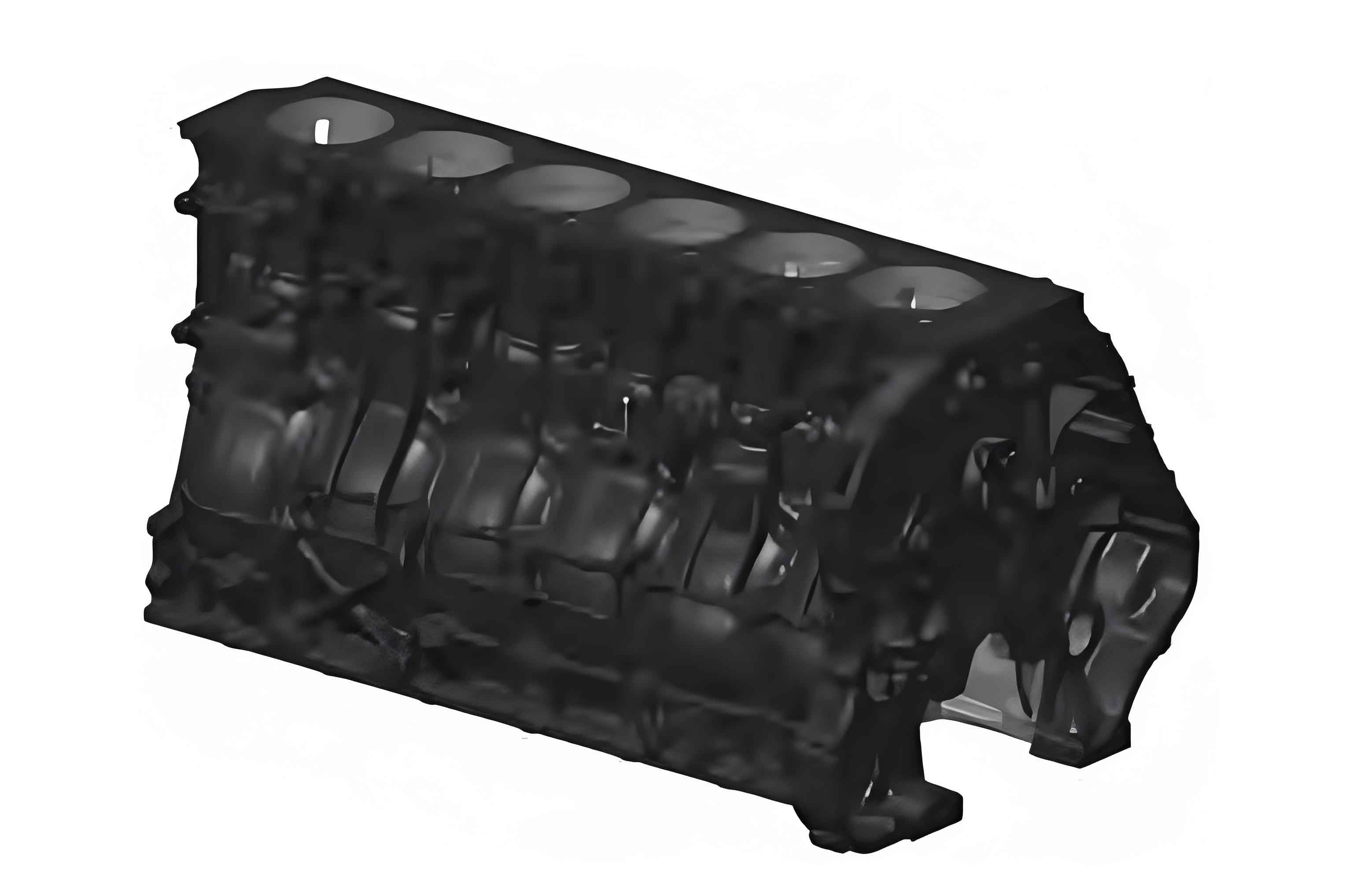
2.1 Structural Complexity
The gear chamber spans a large area, and the castings have minimum dimensions of 900mm × 500mm × 500mm. The structure is complex, with multiple reinforcing ribs on the surface to accommodate high explosive pressures. To achieve lightweight design, the primary wall thickness is only 4 to 5.5mm, and the casting weight ranges from 270 to 400kg. The material used is HT300-RT450 to meet high explosive pressure requirements.
2.2 Quality Requirements
The cylinder blocks must meet stringent internal cavity cleanliness and appearance quality standards. Given their complexity and the high production volume, an automated and streamlined casting production method is employed. This poses significant challenges for process design and production layout, as traditional single-process, point-to-point layouts are insufficient.
2.3 Production Environment
In recent years, our company’s focus has been on core-making and molding processes, with relatively fewer investments and less attention paid to the cleaning process. However, the cleaning process is characterized by harsh working conditions, high labor intensity, and safety risks, which have become bottlenecks hindering our company’s high-quality development.
3. Cleaning Process and Workflow
The current cleaning process primarily involves manual handling using cranes for various operations such as annealing, rough cleaning, grinding, vibrating core removal, coarse polishing, fine cleaning, precision polishing, inspection, and powder coating. Due to the complex structure of the products, internal and external quality is primarily ensured through manual fine cleaning, which requires highly skilled operators, leading to high labor intensity and safety risks.
3.1 Current Process Challenges
As engine requirements for the cleanliness of various waterways and oil passages within the cylinder block increase, the current process fails to meet high-precision dimensional and quality standards.
3.2 Simplified Process Flowchart
| Step | Operation | Method |
|---|---|---|
| 1 | Code Stacking | Manual |
| 2 | Powder Coating | Manual |
| 3 | Precision Polishing | Manual |
| 4 | Inspection | Manual |
| 5 | Fine Cleaning | Manual |
| 6 | Coarse Polishing | Manual |
| 7 | Vibrating Core Removal | Manual |
| 8 | Grinding | Manual |
| 9 | Rough Cleaning | Manual |
| 10 | Annealing Kiln | Manual Handling |
| 11 | Casting Grabbing | Mechanical Hand |
4. Cleaning Process Transformation and Upgrading
To address the challenges faced by the traditional cleaning process, a comprehensive transformation and upgrading plan was devised, focusing on automation and intelligence to improve efficiency and quality assurance.
4.1 Automated Transfer via Robots and Vision Recognition
The current process involves significant manual handling, particularly in grinding and vibrating core removal, which is labor-intensive and hazardous. To achieve automated transfer, the following measures were taken:
4.1.1 Selection of Clamping Points
Given the variety of products and their differing appearances, a uniform clamping method was sought. After comprehensive research, the cylinder bore interior was chosen as the clamping point. This required the castings to be vertically oriented on the conveyor line, enabling the robot clamp to reach into the bore for gripping.
4.1.2 Process Optimization for Automation
To facilitate automation, the following process optimizations were implemented:
- Modification of Overflow Riser Design: The cylindrical overflow riser was redesigned into a flat riser with venting needles, with a thickness not exceeding 4mm. This allowed for better cleaning of the riser root during rough cleaning, enabling vertical placement and transportation of castings on the conveyor line.
- Optimization of Gating System: The three-tiered gating system was redesigned into a two-tiered system, with the internal gate area optimized to ensure smooth pouring without turbulence. This reduced the size of the bottom plane gate, minimizing its impact on the casting’s vertical positioning.
- Addition of Sand Dropping Mechanism: An autonomously designed sand dropping mechanism was added to the rough cleaning process to pre-treat cylinder bore sand accumulation, ensuring the robot clamp could enter.
- Vision Recognition System: A vision recognition system was integrated to assist in positioning, enabling automated handling of workpieces. The vision system identified the workpiece type, position, and status, generating corresponding handling programs and adjusting the coordinate system accordingly.
| Optimization Measure | Purpose |
|---|---|
| Cylindrical to Flat Overflow Riser | Enable vertical placement and transportation |
| Two-tiered Gating System | Ensure smooth pouring and minimize vertical positioning impact |
| Sand Dropping Mechanism | Pre-treat cylinder bore sand accumulation |
| Vision Recognition System | Assist in positioning for automated handling |
4.2 Flexible Intelligent Cleaning Line
A flexible intelligent cleaning line was established using specialized machines, intelligent flexible processing units, and robots, significantly reducing the number of manual operators required for fine cleaning.
4.2.1 Intelligent Grinding Technology
- Robot-Electric Spindle Integration: Robots equipped with electric spindles and diamond grinding wheels achieved automated grinding. Laser alignment scanning compensated for errors due to casting and fixture tolerances, automatically generating suitable grinding programs.
- Automated Tool Change: Different diamond grinding wheels were automatically changed based on the grinding area, ensuring optimal grinding results.
- Overload Protection: When grinding force exceeded safe limits, the system automatically adjusted spindle speed and feed rate, preventing damage.
4.2.2 Integrated Fixture Design
- High Universality: Integrated fixture design allowed for quick adjustment and replacement, compatible with different series of castings.
- Stable Grasping: The design ensured smooth grasping, rapid movement, and convenient control.
| Intelligent Technology | Function |
|---|---|
| Robot-Electric Spindle Integration | Automated grinding with laser alignment |
| Automated Tool Change | Adaptation to different grinding areas |
| Overload Protection | Prevents damage due to excessive force |
| Integrated Fixture Design | Quick adjustment, high universality |
4.2.3 Bus Integration Control Technology
- Intelligent Control and Logistics: Bus control technology optimized the automatic control of each unit, adjusting the logistics mode based on real-time feedback to achieve optimal workflow efficiency and safety.
- Comprehensive Grinding Process Coverage: By analyzing and reasonably matching grinding points between CNC equipment and robot units, an optimal grinding process flow was established.
4.3 Development of Internal Cavity Cleaning System
An internal cavity cleaning system was developed, integrating automatic blowing and shot blasting, significantly improving internal cavity quality.
4.3.1 Equipment Workflow
| Step | Operation |
|---|---|
| 1 | Incoming Material via Conveyor Roller |
| 2 | Casting Type Recognition |
| 3 | Automatic Cleaning Hole Unit |
| 4 | Automatic Blowing Unit |
| 5 | Vision-guided Loading to Shot Blasting Machine |
| 6 | 3D Vision Positioning |
| 7 | Shot Blasting by Robot |
| 8 | Unloading and丸料 Removal |
| 9 | Outgoing Material via Conveyor Roller |
4.3.2 Automatic Recognition Function
Two sets of 2D smart camera systems identified the casting appearance and local characters, enabling automatic program switching for internal cavity cleaning and shot blasting, optimizing production efficiency for multi-product lines.
4.3.3 Automatic Cleaning Hole Unit
This unit ensured that all oil, water, and process holes connecting the internal cavity structure were open, providing input ports for subsequent automatic blowing and shot blasting.
4.3.4 Shot Blasting Process
A dual-station shot blasting process was designed, with two shot blasting robots working in parallel. Each robot independently completed the entire shot blasting process, significantly enhancing productivity. Additionally, a dual-gun toolholder was designed, allowing each robot to carry two shotguns, automatically adjusting their distance based on preset programs and coordinating with robot movements for simultaneous dual-hole shot blasting.
| Component | Function |
|---|---|
| Conveyor Roller | Material transportation |
| Casting Type Recognition | Automatic program switching |
| Automatic Cleaning Hole Unit | Ensures hole openness |
| Automatic Blowing Unit | Cleans internal cavity |
| Shot Blasting Machine | Internal cavity shot blasting |
| 3D Vision Positioning | Precise robot positioning |
5. Conclusion
This article systematically introduced the overall automation cleaning process development for high-end heavy-duty engine cylinder block casting, focusing on automation pathways and equipment. By integrating automation and process improvements, the traditional challenges of harsh working conditions, high labor intensity, and low production efficiency in the cleaning process were addressed, reaching domestic advanced levels.
The implementation of this automated cleaning process not only improves production efficiency and product quality but also lays the foundation for future unmanned cleaning processes, enhancing the competitiveness of engine casting enterprises.