
In our foundry, we have long faced significant challenges with porosity defects in certain castings, leading to high scrap rates and impacting production schedules. Components such as valve caps, bearing covers, and valve covers consistently exhibited porosity rates above 15%, often only detected during machining, causing substantial losses. To address this, we undertook a comprehensive review and improvement of our casting processes under existing conditions, focusing on eliminating porosity. This article details our journey, using a valve cap as a case study, to share insights and methodologies that can help others combat porosity in casting.
Porosity in casting is a pervasive issue that arises from various factors including molten metal properties, gating system design, mold conditions, and venting. In our experience, porosity often manifests as small, round holes with smooth, shiny, or slightly oxidized surfaces, typically concentrated in thin-walled sections or remote areas of the castings. Understanding the root causes is crucial for effective mitigation. We identified two primary contributors: first, the slow flow and excessive cooling of molten iron in thin, elongated sections, leading to reduced fluidity and trapped gases; second, inadequate venting of mold cavities, which fails to expel gases generated during pouring. These factors collectively exacerbate porosity in casting, necessitating targeted工艺 improvements.
To systematically analyze porosity in casting, we developed a theoretical framework based on fluid dynamics and heat transfer. The velocity of molten metal flow can be described by Bernoulli’s principle, modified for viscous fluids: $$v = \sqrt{\frac{2 \Delta P}{\rho} + 2gh – \frac{2 \mu L}{\rho R^2}}$$ where \(v\) is the flow velocity, \(\Delta P\) is the pressure difference, \(\rho\) is the density of molten iron, \(g\) is gravitational acceleration, \(h\) is the height difference, \(\mu\) is the dynamic viscosity, \(L\) is the flow length, and \(R\) is the hydraulic radius. This equation highlights how increased viscosity due to cooling reduces velocity, aggravating porosity in casting. Similarly, heat loss during flow can be approximated by: $$Q = h_c A (T_m – T_mold) t$$ where \(Q\) is the heat loss, \(h_c\) is the convective heat transfer coefficient, \(A\) is the surface area, \(T_m\) is the molten metal temperature, \(T_mold\) is the mold temperature, and \(t\) is the time. Excessive heat loss lowers fluidity, preventing gas bubbles from rising and escaping.
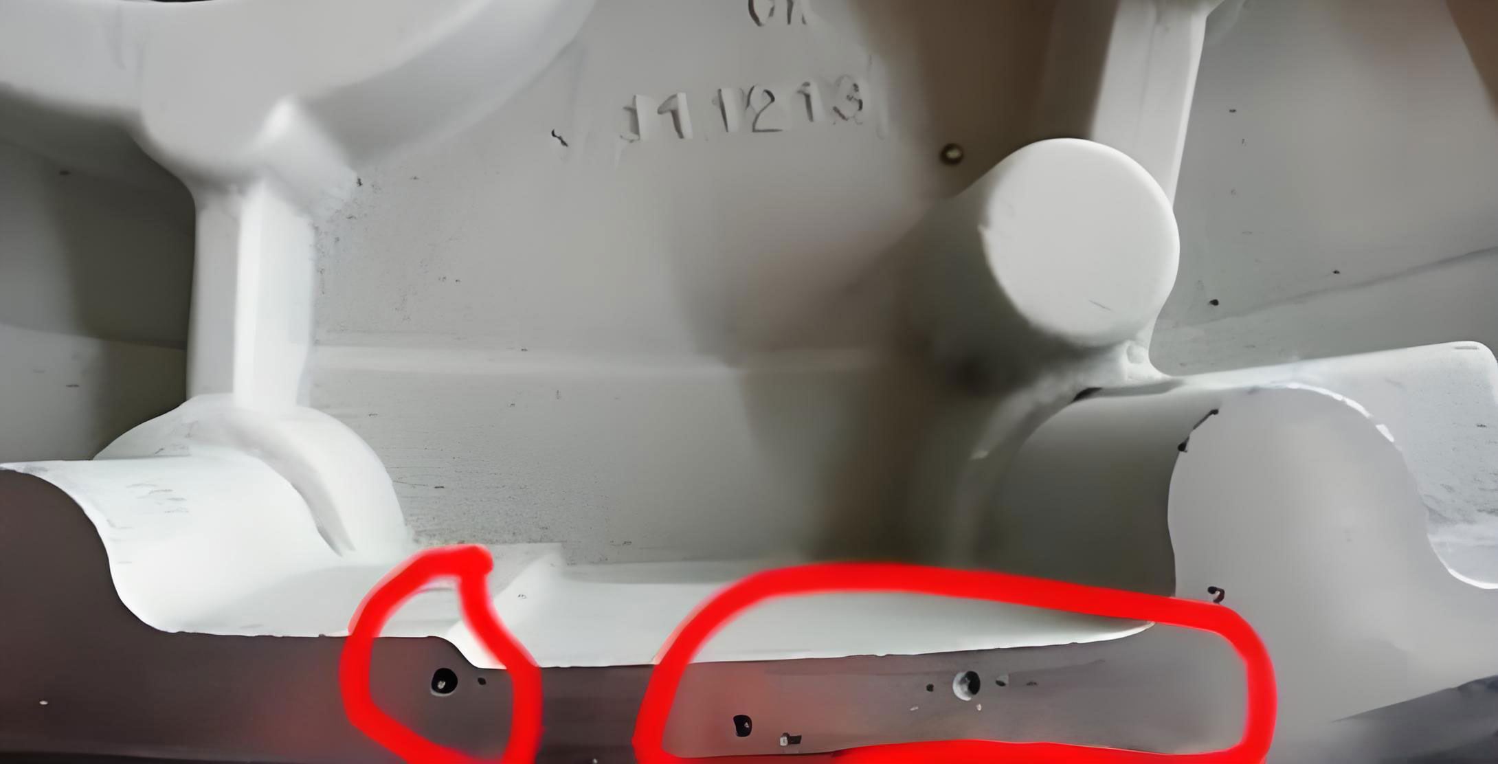
The image above illustrates typical porosity in casting defects, underscoring the need for precise control. In our valve cap castings, made of HT200 gray iron with a weight of 5 kg, the design featured a top-heavy geometry with thin walls as slim as 5 mm connecting the base and head. Our initial process used green sand molding with manual techniques, melting in a cupola furnace with a maximum tapping temperature of 1480°C and a pouring temperature range of 1360–1380°C. The gating system consisted of a single 30 mm diameter sprue, a trapezoidal ingate with dimensions height 20 mm, upper base 35 mm, and lower base 25 mm, and one edge feeder. Venting was limited to one 15 mm exhaust hole at the top of the mold cavity. This setup resulted in widespread porosity in casting at the base, characterized by numerous dispersed pores 1–3 mm in diameter.
We conducted a root-cause analysis, summarizing key factors in Table 1. This table compares the original and improved processes, emphasizing parameters that influence porosity in casting.
| Factor | Original Process | Improved Process | Impact on Porosity in Casting |
|---|---|---|---|
| Sprue Diameter | 30 mm | 40 mm | Increases flow rate, reduces cooling |
| Number of Ingates | 1 | 2 | Enhances simultaneous metal delivery |
| Feeder System | Single edge feeder | Two edge feeders | Improves feeding and reduces turbulence |
| Venting Holes | 1 top hole | Multiple holes and vents | Better gas expulsion, lowers backpressure |
| Pouring Temperature | 1360–1380°C | 1380–1400°C | Maintains higher fluidity |
| Mold Sand Moisture | Standard green sand | Reduced moisture, pre-dried cores | Decreases gas generation |
From this analysis, we derived that porosity in casting is predominantly influenced by flow dynamics and thermal conditions. The modified Bernoulli equation can be extended to account for multiple ingates: $$v_{eff} = \sum_{i=1}^{n} \frac{A_i}{A_{total}} v_i$$ where \(v_{eff}\) is the effective velocity, \(n\) is the number of ingates, \(A_i\) is the cross-sectional area of each ingate, and \(v_i\) is the velocity through each. Increasing \(n\) boosts \(v_{eff}\), ensuring faster and hotter metal reaches critical sections. Additionally, the gas pressure buildup in the mold cavity can be modeled as: $$P_{gas} = \frac{R T_{gas} \dot{m}_{gas}}{V_{cavity}}$$ where \(P_{gas}\) is the gas pressure, \(R\) is the gas constant, \(T_{gas}\) is the gas temperature, \(\dot{m}_{gas}\) is the gas generation rate, and \(V_{cavity}\) is the cavity volume. Enhanced venting reduces \(P_{gas}\), minimizing gas entrapment and porosity in casting.
Implementing the improved process involved several key changes. We increased the sprue diameter to 40 mm to elevate the metal head pressure and flow velocity. Two ingates, identical to the original trapezoidal design, were employed to split the flow, doubling the effective channel area to the base. This design leverages the principle of parallel flow paths to reduce pressure drops, as described by: $$\Delta P_{total} = \frac{1}{\sum_{i=1}^{n} \frac{1}{\Delta P_i}}$$ for parallel systems, where \(\Delta P_i\) is the pressure drop per path. Lower pressure drops maintain higher temperatures, countering porosity in casting. Each ingate fed into an edge feeder, serving as a减压消能冒口 (pressure-reducing and energy-dissipating feeder) that minimizes turbulence, filters slag, and ensures平稳充型 (smooth filling). Venting was augmented with an additional 15 mm exhaust hole at the far end from the sprue, plus numerous vent holes punched in the cope using vent wires. Furthermore, all 11 sand cores were pre-made and air-dried to reduce moisture-related gas generation.
The results were striking. Porosity in casting defects plummeted, with the scrap rate dropping from over 15% to below 5%. We validated this through microscopic examination and pressure testing, confirming that the castings met the required specifications of no leakage under 1.6 MPa hydrostatic pressure for 3 minutes. To quantify the improvement, we used a porosity index defined as: $$PI = \frac{N_{pores} \times \bar{d}}{A_{area}}$$ where \(PI\) is the porosity index, \(N_{pores}\) is the number of pores per unit area, \(\bar{d}\) is the average pore diameter, and \(A_{area}\) is the inspected area. As shown in Table 2, the improved process yielded a significantly lower PI, underscoring its efficacy against porosity in casting.
| Process Version | Porosity Index (PI) | Scrap Rate Due to Porosity | Average Pore Diameter (mm) |
|---|---|---|---|
| Original | 0.45 | >15% | 2.0 |
| Improved | 0.08 | <5% | 0.5 |
We extended these principles to other castings like bearing covers and valve covers, achieving similar success in reducing porosity in casting. This highlights the universality of our approach: for thin-walled and irregularly shaped castings, it is essential to optimize gating to enhance simultaneous metal delivery to vulnerable areas, incorporate feeders that dampen turbulence and remove slag, and strengthen mold venting while minimizing gas sources. We also explored the role of molten metal composition, particularly for gray iron, where carbon equivalent (CE) affects fluidity. CE is calculated as: $$CE = \%C + 0.33(\%Si + \%P)$$ Higher CE improves fluidity, reducing porosity in casting. In our case, maintaining CE around 4.2–4.3 complemented the process changes.
Beyond practical adjustments, we delved into simulation tools to predict and prevent porosity in casting. Computational fluid dynamics (CFD) models can simulate mold filling and solidification, identifying hotspots for gas entrapment. The governing Navier-Stokes equations for incompressible flow: $$\rho \left( \frac{\partial \mathbf{v}}{\partial t} + \mathbf{v} \cdot \nabla \mathbf{v} \right) = -\nabla P + \mu \nabla^2 \mathbf{v} + \rho \mathbf{g}$$ coupled with the energy equation: $$\rho c_p \left( \frac{\partial T}{\partial t} + \mathbf{v} \cdot \nabla T \right) = k \nabla^2 T$$ where \(c_p\) is specific heat and \(k\) is thermal conductivity, allow us to optimize gating designs virtually. Although we relied on empirical methods initially, such simulations are now integral to our strategy for combating porosity in casting.
Another critical aspect is mold material selection. Green sand, while economical, can contribute to porosity in casting due to moisture and organic content. We evaluated alternative binders, such as furan resins, but focused on refining existing clay-bonded sand by reducing water content to 3–4% and ensuring proper compaction. The gas permeability of the mold, defined as: $$GP = \frac{V \cdot L}{A \cdot t \cdot \Delta P}$$ where \(GP\) is gas permeability, \(V\) is gas volume, \(L\) is sample thickness, \(A\) is cross-sectional area, \(t\) is time, and \(\Delta P\) is pressure difference, was increased through adjusted sand mixtures, further mitigating porosity in casting.
In总结, our experience demonstrates that porosity in casting is a multifaceted problem solvable through integrated工艺 enhancements. Key takeaways include: increasing gating dimensions to boost flow velocity and temperature; utilizing multiple ingates and feeders to ensure uniform, turbulent-free filling; and maximizing venting capacity to expel gases. We encourage foundries to adopt a data-driven approach, using formulas and tables like those presented here to guide decisions. Continuous monitoring and adaptation are vital, as each casting presents unique challenges. By prioritizing these factors, we have consistently produced sound, dense castings free from porosity, turning a persistent defect into a controlled variable. The battle against porosity in casting is ongoing, but with systematic efforts, it can be decisively won.
To further elaborate on the science behind porosity in casting, let’s consider the nucleation and growth of gas bubbles. According to classical nucleation theory, the critical radius \(r_c\) for a gas bubble to form in molten metal is given by: $$r_c = \frac{2 \sigma}{\Delta P_{sup}}$$ where \(\sigma\) is the surface tension and \(\Delta P_{sup}\) is the supersaturation pressure of the gas. In iron castings, gases like hydrogen and nitrogen can dissolve during melting and precipitate upon cooling, leading to porosity in casting. The solubility follows Sievert’s law: $$S = k \sqrt{P}$$ where \(S\) is solubility, \(k\) is a constant, and \(P\) is the partial pressure. Rapid cooling increases supersaturation, promoting bubble formation. Our process improvements, by maintaining higher temperatures and faster solidification fronts, reduce supersaturation and bubble nucleation sites.
We also investigated the effect of pouring speed on porosity in casting. The pouring time \(t_p\) can be estimated as: $$t_p = \frac{V_{casting}}{A_{ingate} \cdot v_{ingate}}$$ where \(V_{casting}\) is the casting volume, \(A_{ingate}\) is the total ingate area, and \(v_{ingate}\) is the ingate velocity. Shorter \(t_p\) minimizes heat loss, but excessively high speeds can cause turbulence. Our dual-ingate system balanced this, achieving an optimal \(t_p\) of 8–10 seconds, compared to 15–18 seconds originally. This aligns with research showing that porosity in casting is minimized when the Reynolds number \(Re = \frac{\rho v D}{\mu}\) is kept below 2000 to ensure laminar flow, preventing gas entrainment.
In terms of mold cavity排气, we designed vent networks based on Darcy’s law for gas flow through porous media: $$Q_{gas} = \frac{K A_{vent} \Delta P_{gas}}{\mu_{gas} L_{vent}}$$ where \(Q_{gas}\) is the gas flow rate, \(K\) is permeability, \(A_{vent}\) is vent area, \(\Delta P_{gas}\) is the pressure difference, \(\mu_{gas}\) is gas viscosity, and \(L_{vent}\) is vent length. By increasing \(A_{vent}\) through additional holes and using finer vent wires, we boosted \(Q_{gas}\), effectively lowering cavity pressure and reducing porosity in casting. Table 3 summarizes venting parameters before and after improvement.
| Venting Parameter | Original Process | Improved Process | Effect on Porosity in Casting |
|---|---|---|---|
| Total Vent Area | 176.7 mm² (one 15 mm hole) | 353.4 mm² (two 15 mm holes plus multiple small vents) | Doubled gas expulsion capacity |
| Vent Location | Top only | Top and far end | Prevents gas trapping in remote areas |
| Core Drying | Minimal | Pre-dried for 24 hours | Reduces core gas generation by ~30% |
Furthermore, we examined the role of inoculants in gray iron to enhance graphite formation, which can help offset porosity in casting by providing escape paths for gases. Adding ferrosilicon inoculants promotes type A graphite, improving density. The inoculant effect can be quantified by the graphite nodule count, which we measured metallographically. Combined with our gating modifications, this contributed to a more homogeneous microstructure, less prone to porosity in casting.
Looking forward, we are experimenting with real-time monitoring systems, such as thermal cameras and pressure sensors, to detect early signs of porosity in casting during production. These technologies, coupled with machine learning algorithms, could predict defects based on parameters like temperature gradients and flow patterns. The integration of Industry 4.0 principles into foundry operations holds promise for near-zero defect rates, making porosity in casting a relic of the past.
In conclusion, our journey to eliminate porosity in casting underscores the importance of a holistic approach. By blending theoretical insights with practical adjustments—from gating design and venting to metal treatment and process control—we transformed a chronic problem into a manageable one. The key lies in understanding the interplay between fluid dynamics, heat transfer, and gas behavior, and then applying that knowledge to tailor solutions for each casting. We hope this detailed account inspires others to tackle porosity in casting with similar rigor and innovation, driving the foundry industry toward higher quality and efficiency.