
In my work on the compression system guide support, I have dealt with a component that plays a critical role in related assemblies. The guide support is a main load-bearing part that experiences the rod-drop force when the choke plug assembly and the secondary source assembly fall inside the reactor. At present, the conventional manufacturing route for this guide support involves machining individual pieces and then welding them together. Although the welded assembly can meet basic strength requirements, the welded joints remain a potential weak point. To improve the overall strength and structural integrity, I focused on a single-piece precision casting solution. This article presents my detailed precision casting scheme based on the lost-wax silica sol process. The scheme covers wax pattern mold design, wax pattern manufacturing, shell making, melting and pouring, heat treatment, and machining. Throughout this work, the term precision casting is used to describe the entire investment casting route that enables near-net-shape production of the complex guide support.
The guide support consists of two major portions: a guide tube and a support plate. The guide tube is a hollow cylindrical structure. Its upper section contains a cylindrical bore, its middle section contains a conical transition bore, and its lower section contains a small cylindrical bore. The lower end of the guide tube connects to a square support plate. The support plate has a ribbed hole structure with four large flow holes and twenty-four assembly holes arranged at specific orientations. This geometry is complex, and its successful production requires a robust precision casting approach. The combination of a long cylindrical tube and a thin ribbed plate makes the casting difficult because of feeding, solidification, and distortion risks. My goal was to establish a repeatable precision casting process that could deliver a sound casting with the required dimensional accuracy and internal quality.
1. Design of the Wax Pattern Mold
My first step in the precision casting route was to analyze the structure of the guide support and to define a preliminary pouring system. I divided the product into two functional regions for mold design: the cylindrical product portion and the main product body portion. To simplify the mold structure, to facilitate wax pattern removal, and to prevent wax pattern deformation, I adopted a split mold design in which the main product body is divided into two parts that are removed separately. Because the cylindrical portion is relatively thick and large, I also designed a cold wax loose core to accelerate wax pattern cooling and to prevent shrinkage deformation. In addition, the gate used for tree assembly had to be integrated into the mold design so that the wax patterns could be assembled conveniently. The precision casting mold structure therefore includes the main body split, the cold wax loose core, and the gate features.
From a thermal standpoint, the mold design must account for the volumetric shrinkage of the wax. The linear shrinkage of the wax pattern can be expressed as:
$$ \epsilon_w = \frac{L_m – L_p}{L_m} \times 100\% $$
where \( \epsilon_w \) is the wax shrinkage, \( L_m \) is the mold cavity dimension, and \( L_p \) is the wax pattern dimension. I used this relationship to compensate the mold cavity dimensions. The cold wax loose core is especially important because the thick cylindrical section would otherwise cool slowly and develop surface sinks or internal voids. By using a cold core, I increased the cooling rate in the thick section, which helped the wax pattern maintain its shape. In my experience, a well-designed mold for precision casting must balance easy removal with adequate constraint to prevent distortion.
The split mold design also affects the parting line. I placed the parting line along a region that would later be machined or that would not compromise the functional surfaces. The gate was positioned to ensure that the molten metal would fill the thin plate ribs and the cylindrical tube without premature freezing. The pouring system was preliminarily designed with a cross-shaped header for tree assembly, which is described later. This design choice was made to ensure sufficient steel volume for feeding the main gate and to provide adequate flow to the small gates around the periphery.
2. Wax Pattern Manufacturing
Wax pattern manufacturing is a decisive step in precision casting because any defect in the wax pattern is likely to be reproduced in the final casting. The main challenge is to prevent wax pattern deformation. During wax injection, I strictly controlled the process parameters. The injection time and pressure must be sufficient to avoid surface depressions. The wax pattern must be handled carefully during removal to avoid deformation. After removal, the wax pattern is placed in water for cooling. Once it is completely cooled, it is arranged neatly to prevent collision damage. The following table summarizes the wax injection parameters that I used.
| Parameter | Requirement |
|---|---|
| Storage wax cylinder temperature / °C | 72 ± 3 |
| Injection wax cylinder temperature / °C | 52 ± 2 |
| Injection time / s | 30–40 |
| Cooling time / s | 0 |
| Injection pressure / (kg/cm²) | 22–25 |
| Cooling method | Water cooling |
| Placement method | Neat arrangement |
| Wax block | No |
| Ceramic core or urea core | None |
| Wax shaping fixture | None |
After injection, I performed wax pattern repair. The parting line must be smoothed, and the wax pattern surface must be clean and free of tool marks. After repair, the two wax pattern halves are joined. During joining, the positioning openings must be fully aligned. I used bonding wax to firmly bond the two halves and then dropped hot wax liquid into the joint to ensure complete fusion. After complete cooling, any excess wax droplets were scraped flat. It is important that the product surface has no depressions or protrusions. This step is critical for precision casting because surface defects on the wax pattern directly affect the surface quality of the final casting.
After the wax patterns were completed, I assembled them into a tree. Based on the product structure, I used a cross-shaped header for tree assembly. This arrangement ensures that the main gate has enough steel volume to meet feeding requirements and that the small gates around the periphery have sufficient steel flow. When assembling the tree, I selected an appropriate gate rod. The wax patterns were placed uniformly on the tree. The completed tree must be clean and free of dust. The assembly must have no virtual welding, gaps, or wax droplets. The gate rod must have no holes, flashes, or sharp edges. It is strictly forbidden to assemble the tree while the header or product carries water. For test samples, I designed the sampling position in the longitudinal direction during wax tree assembly. This practice helped me evaluate the casting quality in a representative section.
The tree assembly geometry can be approximated by a simple flow resistance model. For a sprue of length \( L \) and diameter \( D \), the pressure drop \( \Delta P \) for a laminar flow of molten metal can be estimated as:
$$ \Delta P = \frac{128 \mu L Q}{\pi D^4} $$
where \( \mu \) is the dynamic viscosity of the molten metal, and \( Q \) is the volumetric flow rate. Although this equation is simplified, it reminded me that larger gates reduce pressure drop but also increase metal consumption. The cross-shaped header provided a good compromise for this precision casting geometry.
3. Shell Making
Shell making is another core step in the precision casting process. The shell must have sufficient strength and permeability to withstand wax removal, burnout, and pouring. I controlled the slurry viscosity strictly because the face coat slurry has a major influence on the surface quality of the product. The shell making process parameters are listed in the following table.
| Shell layer | Slurry material | Slurry viscosity / s | Sand material | Room temperature / °C | Humidity RH / % | Drying time / h |
|---|---|---|---|---|---|---|
| Face layer | Zircon powder | 36–40 | Zircon sand 80–120 mesh | 20–26 | 60–70 | 6–12 |
| Second layer | Mullite powder | 20–24 | Mullite sand 60–80 mesh | 20–26 | 40–60 | ≥4 |
| Third layer | Mullite powder | 12–16 | Mullite sand 16–30 mesh | 20–26 | 40–60 | ≥4 |
| Fourth layer | Mullite powder | 12–16 | Mullite sand 16–30 mesh | 20–26 | 40–60 | ≥4 |
| Fifth layer | Mullite powder | 12–16 | Mullite sand 16–30 mesh | 20–26 | 40–60 | ≥4 |
| Half layer | Mullite powder | 8–12 | – | 20–26 | 40–60 | ≥4 |
The slurry viscosity was measured using a Zahn cup. The measured flow time characterizes the slurry viscosity. From the second layer onward, I used a robotic arm for shell making. The use of a robotic arm reduced the labor intensity of the workers and produced a more uniform shell thickness. The shell density was slightly better than that achieved by manual shell making. The robot could work continuously for 24 hours, and the quick-drying room shortened the shell drying time. After the product was put on the line, it could usually be taken off after 24 hours. The shell making cycle was only one quarter of the conventional manual shell making cycle, which greatly improved production efficiency. This improvement is one of the key advantages of my precision casting scheme.
After the shell was dried, I used a steam dewaxing autoclave to remove the wax from the shell. Before dewaxing, the flash on the gate cup must be cleaned. The dewaxing parameters were set strictly according to the following table. After dewaxing, the gate cup must be placed downward to prevent dust and other debris from entering the shell. I also frequently checked and cleaned the filter screen, and replaced it when necessary to maintain effective filtration.
| Parameter | Requirement |
|---|---|
| Placement method | Gate cup downward |
| Pressure / MPa | 0.5–0.6 |
| Pressure release time / s | > 50 |
| Dewaxing time / min | 10–15 |
| Temperature setting / °C | 150–160 |
The dewaxing process can be modeled as a heat transfer problem. The time required to melt the wax depends on the wax thermal conductivity \( k \), the density \( \rho \), the latent heat \( L_f \), and the temperature difference \( \Delta T \). A simplified relation is:
$$ t_{dewax} \propto \frac{\rho L_f \delta^2}{k \Delta T} $$
where \( \delta \) is the characteristic thickness of the wax section. This relationship helped me understand why the thick cylindrical section required longer dewaxing time and why the cold wax core was beneficial during wax injection.
4. Melting and Pouring
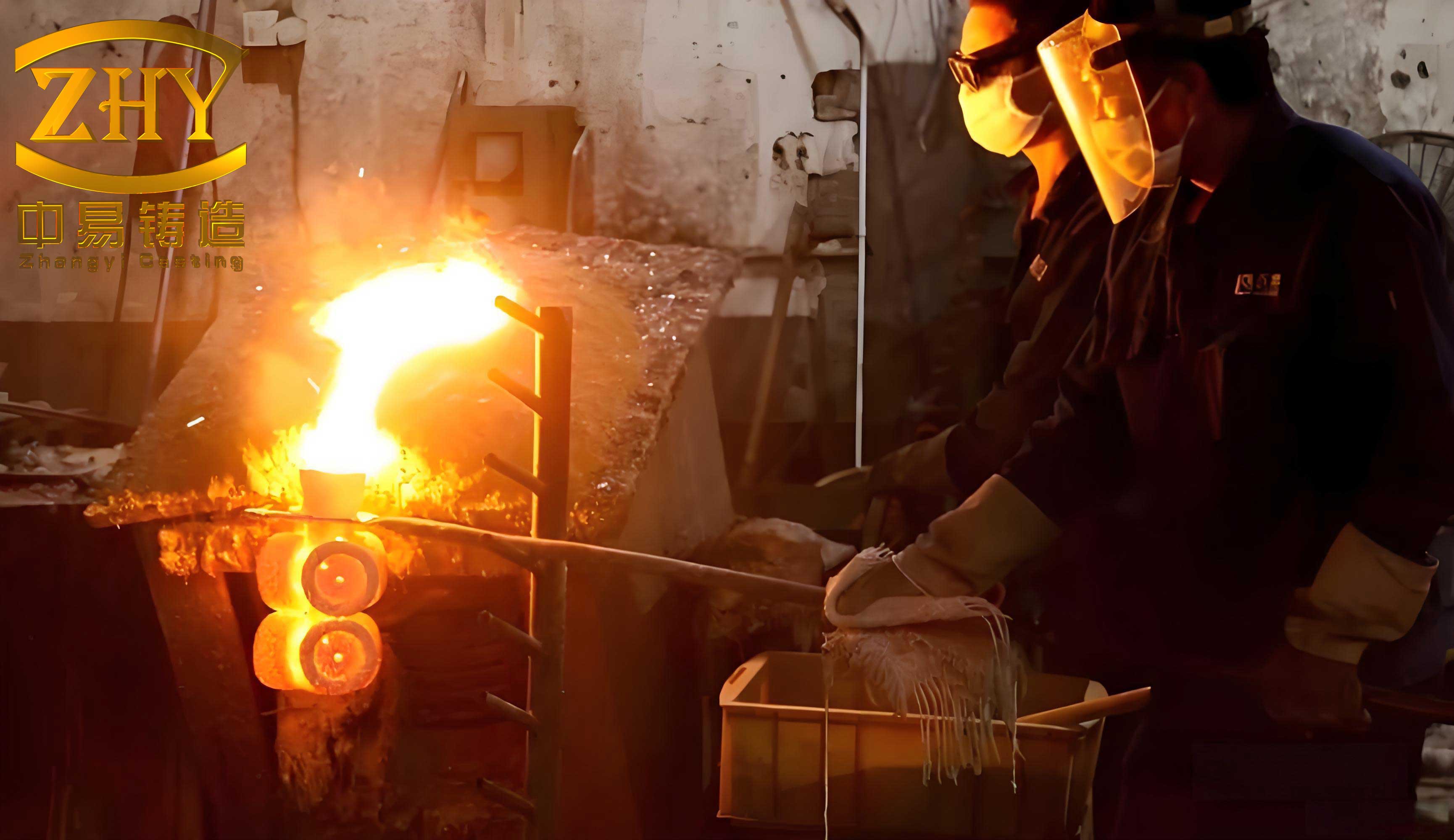
Melting is the most critical step in the precision casting process. The guide support must meet radiographic inspection requirements, so the internal quality of the product must be very high. When formulating the process, I fully considered various factors. The melting parameters are listed in the following table. During melting, the slag and residual molten steel in the furnace must be completely cleaned to prevent residual elements from affecting the steel composition. The charge was prepared strictly according to the material batching list for the guide support to ensure that the material composition was qualified.
| Parameter | Requirement |
|---|---|
| Roasting temperature / °C | 1100 ± 20 |
| Roasting time / min | ≥ 90 |
| New-to-old material mass ratio | ≥ 60:40 |
| Pouring temperature / °C | 1550 ± 10 |
| Slag removal method | Electrostatic slagging |
| Medium deoxidation | Electrolytic manganese, ferrosilicon, and calcium silicon each 50–70 g |
| Heating and insulating agent | Yes |
| Pressing box | No |
| Cooling method | Wet sand bed cooling |
The guide support material is CF3 cast steel. The typical chemical composition range of CF3 cast steel is given in the following table. I used this range to verify the charge composition and to ensure that the final casting met the specification.
| Element | C | Mn | Si | P | S | Cr | Ni | Mo |
|---|---|---|---|---|---|---|---|---|
| Typical range / wt% | ≤ 0.03 | ≤ 1.50 | ≤ 1.50 | ≤ 0.04 | ≤ 0.04 | 17.0–21.0 | 8.0–12.0 | ≤ 0.50 |
Because the cylindrical portion of the guide support is relatively long, the casting is prone to internal porosity caused by insufficient feeding. In addition, the ribs around the support plate are relatively thin, making them susceptible to cold shuts and incomplete filling. Therefore, the pouring temperature must be strictly controlled at 1550 °C ± 10 °C. At the same time, during pouring, I used a wet sand bed to cool the lower half of the shell and wrapped the header portion with insulation cotton. This approach ensured that the feeding channel remained open and that no internal defects formed. The wet sand bed accelerated cooling in the lower region, while the insulated header remained hot and continued to feed the casting. This directional solidification strategy is essential in precision casting of complex geometries.
The feeding distance can be estimated using the modulus method. The modulus \( M \) of a section is defined as:
$$ M = \frac{V}{A} $$
where \( V \) is the volume and \( A \) is the surface area of the section. A larger modulus means slower cooling. For effective feeding, the feeder modulus \( M_f \) should satisfy:
$$ M_f \geq 1.2 M_c $$
where \( M_c \) is the modulus of the casting section being fed. I used this criterion to verify the cross-shaped header and the gate sizes. The header had a larger modulus than the thickest section of the guide tube, which helped ensure adequate feeding.
The solidification time \( t_s \) can be approximated by:
$$ t_s = k M^n $$
where \( k \) is a constant depending on the material and mold, and \( n \) is typically between 1.5 and 2.0. This relation further supported the use of the wet sand bed and insulation cotton to control cooling rates in different regions. By making the lower part cool faster and the header cool slower, I promoted directional solidification from the bottom to the top. This is a classic principle in precision casting and is especially important for the guide support.
5. Heat Treatment
After pouring and shell removal, the guide support castings were subjected to heat treatment. The raw material is CF3 cast steel, and the cast product requires quenching. I used a sealed pit resistance furnace with an air atmosphere. The holding temperature was 1100 °C, and the holding time was 80 min. The products were placed uniformly in the furnace to avoid stacking. After coming out of the furnace, the products were quickly put into cooling water so that they could cool rapidly. The initial temperature of the cooling water must not exceed 50 °C. The products were taken out of the water only after they were completely cooled. The heat treatment curve is summarized in the following table.
| Parameter | Requirement |
|---|---|
| Material | CF3 cast steel |
| Furnace type | Sealed pit resistance furnace |
| Atmosphere | Air |
| Heating temperature | 1100 °C ± 20 °C |
| Holding time | 80 min ± 20 min |
| Cooling method | Water quenching |
| Initial cooling water temperature | ≤ 50 °C |
The quenching process can be described by the cooling rate \( \dot{T} \):
$$ \dot{T} = \frac{dT}{dt} $$
For CF3 cast steel, a sufficiently high cooling rate is necessary to obtain a fully austenitic or martensitic structure, depending on the exact composition and requirements. In my process, the water quenching provided the required cooling rate. The uniform placement of the products ensured that each casting experienced a similar thermal history. This step is important for achieving consistent mechanical properties in the precision casting.
6. Machining
After heat treatment, the guide support castings were machined. According to the product requirements, the upper and lower surfaces of the support plate, the guide tube body, and the twenty-four holes needed machining. The machining must ensure that the product meets perpendicularity, flatness, and positional tolerance requirements. The main machining difficulty was ensuring the positional relationship between the twenty-four small holes and the datum A cylinder. Because of the special structure of the product, the cylindrical portion had to be turned to size on a CNC lathe, and then the twenty-four holes were machined on a machining center. To meet the drawing requirements, I designed a dedicated machining fixture. This fixture ensured that the positional tolerance of the twenty-four holes was qualified and that the perpendicularity between the datum A cylinder and the datum C plane was maintained.
The positional tolerance can be expressed as:
$$ T_{pos} = 2 \sqrt{ (x_i – x_0)^2 + (y_i – y_0)^2 } $$
where \( (x_0, y_0) \) is the theoretical position and \( (x_i, y_i) \) is the actual position of the hole center. The fixture reduced the deviation by providing a rigid and accurate locating scheme. The perpendicularity error \( \delta_\perp \) can be approximated from the measured angle \( \theta \):
$$ \delta_\perp = L \tan \theta $$
where \( L \) is the height of the measured feature. By controlling the fixture and the machining sequence, I kept both errors within the specified limits. The machining step is the final operation that brings the precision casting to the required dimensions. Without a sound casting, machining cannot compensate for internal defects. Therefore, the entire precision casting route must be controlled from wax pattern to heat treatment.
7. Process Verification and Quality Control
To verify the precision casting scheme, I performed a series of tests on the guide support produced by this route. The tests included chemical composition analysis, metallographic examination, penetrant testing, radiographic testing, intergranular corrosion testing, mechanical property testing, and hardness testing. The results met the technical requirements of the drawing. The chemical composition was within the specified range for CF3 cast steel. The metallographic structure was sound, and the penetrant and radiographic inspections showed no unacceptable indications. The mechanical properties and hardness were also satisfactory. These results confirmed that the lost-wax silica sol precision casting route followed by heat treatment and machining can stably produce the guide support.
I also evaluated the production efficiency and yield. The original scheme used a combination of existing headers and wax strips, which made the header structure complex, reduced production efficiency, and lowered the yield. For future batch production, a new header mold can be designed according to the process requirements. This would simplify the structure, improve production efficiency, and increase the yield. In my view, the precision casting route has significant potential for further optimization.
The overall process flow can be summarized as follows:
| Step | Main operation | Key control points |
|---|---|---|
| 1 | Wax pattern mold design | Split mold, cold wax core, gate layout |
| 2 | Wax pattern manufacturing | Injection parameters, repair, joining, tree assembly |
| 3 | Shell making | Slurry viscosity, layer drying, robotic shell building |
| 4 | Dewaxing | Pressure, time, temperature, downward placement |
| 5 | Melting and pouring | Charge composition, pouring temperature, directional cooling |
| 6 | Heat treatment | 1100 °C, 80 min, water quenching |
| 7 | Machining | CNC turning, machining center, dedicated fixture |
| 8 | Inspection | Chemical, metallographic, penetrant, radiographic, mechanical |
The success of this precision casting scheme depends on strict adherence to the parameters in each step. Small deviations in wax injection temperature, slurry viscosity, pouring temperature, or quenching rate can lead to defects. For example, if the pouring temperature is too low, the thin ribs may not fill completely. If the pouring temperature is too high, the grain size may become coarse, and the mechanical properties may deteriorate. The optimal pouring temperature of 1550 °C ± 10 °C was determined through trials and is well suited to the CF3 cast steel and the shell system used in this precision casting process.
Another important factor is the shell strength. The shell must withstand the weight of the molten metal during pouring. The static pressure at the bottom of the shell can be estimated by:
$$ P = \rho g h $$
where \( \rho \) is the density of the molten steel, \( g \) is the gravitational acceleration, and \( h \) is the height of the molten metal column. For a typical pouring height of 0.3 m, the pressure is about 0.023 MPa. Although this pressure is modest, the shell must also resist thermal shock and mechanical handling. The multilayer shell with zircon face coat and mullite backup layers provided adequate strength and thermal stability. The robotic shell making improved the consistency of the shell thickness, which directly influenced the thermal gradients during solidification.
The wax pattern shrinkage and casting shrinkage must be compensated in the mold. The total shrinkage \( \epsilon_{total} \) is the sum of the wax shrinkage \( \epsilon_w \) and the casting shrinkage \( \epsilon_c \):
$$ \epsilon_{total} = \epsilon_w + \epsilon_c $$
For CF3 cast steel, the casting shrinkage is typically around 2%. The wax shrinkage depends on the wax formulation and injection parameters. I used a combined shrinkage allowance of approximately 2.5% to 3.0% on the mold dimensions. This allowance was verified by measuring the final castings. If the shrinkage allowance is too small, the final casting will be oversized. If it is too large, the casting will be undersized. The precision casting route requires careful dimensional control at every step.
In addition to dimensional control, internal soundness is critical. The radiographic inspection requires that the casting be free of unacceptable porosity, shrinkage, and inclusions. The directional solidification achieved by the wet sand bed and insulated header was essential. The wet sand bed increased the cooling rate at the bottom of the shell, while the insulation cotton reduced the cooling rate at the top. This created a positive thermal gradient from bottom to top, which promoted feeding through the gate and header. The modulus criterion \( M_f \geq 1.2 M_c \) was satisfied for all critical sections. The result was a sound casting with no significant internal defects.
The heat treatment after casting also affects the final properties. The CF3 cast steel is an austenitic stainless steel. The quenching treatment at 1100 °C followed by water cooling is intended to dissolve carbides and obtain a homogeneous austenitic structure. If the holding time is too short, carbides may remain undissolved. If the holding time is too long, grain growth may occur. The holding time of 80 min at 1100 °C was selected based on the section thickness and the furnace characteristics. The rapid water quenching prevented the precipitation of carbides at grain boundaries, which is important for intergranular corrosion resistance. The initial water temperature of ≤ 50 °C ensured a sufficiently high cooling rate. The uniform placement of the castings in the furnace ensured that each part experienced the same thermal cycle.
The machining operation after heat treatment must not introduce excessive residual stresses or distortion. The dedicated fixture provided rigid support and accurate location. The CNC turning of the cylindrical portion ensured that the datum A cylinder was concentric and perpendicular to the support plate. The machining center then drilled and reamed the twenty-four holes in one setup, which minimized positional errors. The positional tolerance and perpendicularity were verified using a coordinate measuring machine. The results showed that the machining accuracy met the drawing requirements. This confirms that the combination of precision casting and precision machining is capable of producing the complex guide support.
8. Comparison with the Welded Assembly
To highlight the benefits of the precision casting route, I compared it with the conventional welded assembly. The welded assembly involves machining the guide tube and the support plate separately and then welding them together. The welded joint can be a weak link, especially under dynamic loading. The heat-affected zone may have reduced mechanical properties. In contrast, the precision casting route produces a single-piece component with no welded joints. The load path is continuous, and the strength is more uniform. The precision casting also reduces the number of manufacturing steps and the associated handling. However, the precision casting route requires careful process control to avoid internal defects and distortion. The comparison is summarized in the following table.
| Aspect | Welded assembly | Precision casting |
|---|---|---|
| Number of pieces | Multiple | Single piece |
| Joint strength | Limited by weld | Continuous base material |
| Heat-affected zone | Present | None |
| Dimensional control | Machining after welding | Near-net shape, less machining |
| Internal quality | Depends on weld quality | Depends on casting solidification |
| Production cycle | Moderate | Longer for first article, shorter for batch |
| Material utilization | Moderate | Higher with optimized gates |
My experience shows that the precision casting route is superior for this component because it eliminates the welded joint and provides a more integral structure. The initial development cost is higher, but the batch production cost can be lower if the process is optimized. The new header mold mentioned earlier is one example of how the precision casting route can be improved for batch production.
9. Further Optimization Opportunities
Although the current precision casting scheme is successful, I identified several opportunities for further optimization. First, the header structure can be redesigned to simplify tree assembly and improve yield. The existing header is assembled from wax strips, which is labor-intensive and can introduce variability. A dedicated header mold would produce a consistent header with optimized feeding channels. Second, the robotic shell making can be further automated with online viscosity monitoring and adaptive drying control. Third, the pouring process can be instrumented with thermal cameras to monitor the solidification front and to adjust the cooling conditions in real time. Fourth, the heat treatment can be optimized by using a vacuum furnace or a controlled atmosphere furnace to reduce surface oxidation. Fifth, the machining fixture can be improved with quick-change features to reduce setup time. These improvements would further enhance the precision casting process and reduce production costs.
From a modeling perspective, the solidification process can be simulated using finite element analysis. The heat transfer equation governing solidification is:
$$ \rho C_p \frac{\partial T}{\partial t} = \nabla \cdot (k \nabla T) + Q $$
where \( \rho \) is the density, \( C_p \) is the specific heat, \( k \) is the thermal conductivity, and \( Q \) is the latent heat source term. By solving this equation with appropriate boundary conditions, the solidification time and the location of the last solidified region can be predicted. This would allow the gate and header design to be optimized without extensive trial and error. I recommend using such simulations in future precision casting developments.
The thermo-mechanical behavior during quenching can also be simulated. The stresses generated during rapid cooling can cause distortion or cracking. The heat transfer coefficient \( h \) at the surface during water quenching is a key parameter. The Biot number \( Bi \) indicates whether the cooling is convection-controlled or conduction-controlled:
$$ Bi = \frac{h L_c}{k} $$
where \( L_c \) is the characteristic length. For water quenching of CF3 cast steel, \( Bi \) is typically greater than 1, indicating that conduction within the part is important. This means that the cooling rate varies with section thickness. The thin ribs cool faster than the thick tube. This differential cooling can cause residual stresses. The uniform placement and the controlled water temperature help mitigate these effects. Further optimization could involve staged quenching or interrupted quenching to reduce residual stresses while still achieving the desired microstructure.
10. Conclusion
The precision casting scheme I developed for the compression system guide support provides a single-piece, high-strength component that meets the demanding requirements of the application. The lost-wax silica sol precision casting route, combined with heat treatment and machining, has been verified by chemical, metallographic, penetrant, radiographic, intergranular corrosion, mechanical, and hardness tests. The results confirm that the process can stably produce the guide support. The key control points are wax pattern deformation prevention, shell quality, pouring temperature, directional solidification, and quenching. The use of a cold wax core, a cross-shaped header, a robotic shell-making system, a wet sand bed with insulated header, and a dedicated machining fixture are the main technical features of the scheme. This precision casting approach can be applied to similar components with complex geometries and high internal quality requirements. I believe that further optimization of the header design, process automation, and simulation-based process control will make the precision casting route even more efficient and cost-effective.
In summary, the precision casting of the guide support is not merely a manufacturing method; it is a comprehensive engineering solution that integrates mold design, wax injection, shell building, melting, pouring, heat treatment, and machining. Each step must be controlled within narrow limits. The parameters and tables presented in this article provide a practical baseline for implementing this precision casting scheme. With continued refinement, the process can achieve higher yield and shorter cycle time, making it suitable for large-scale production. The successful application of this precision casting route also demonstrates the value of investment casting for critical components in nuclear and other high-reliability industries.