
Abstract:
This paper delves into the precision casting process of an exhaust manifold, leveraging advanced simulation software (ProCAST) to analyze the filling and solidification processes, predict defect distributions, and ultimately design an optimized casting process. The research aims to eliminate defects and ensure high-quality castings, meeting the stringent requirements of modern engine technology.
1. Introduction
With advancements in engine technology, fuel efficiency has increased, leading to a substantial rise in exhaust temperatures. Consequently, the quality requirements for exhaust manifolds have become more stringent. Exhaust manifolds feature complex structures with varying wall thicknesses, numerous isolated hot spots, and challenges in placing risers, making casting production difficult. Precision casting, renowned for producing castings with high dimensional accuracy, surface quality, and intricate shapes, is widely used in the production of exhaust manifolds.
2. Casting Structure and Material
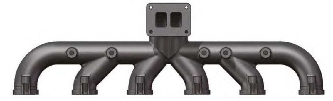
The exhaust manifold has dimensions of 845.85 mm × 105.68 mm × 247.57 mm. It comprises two main pipes on the left and right sides, each connecting to three manifolds, converging at a central main flange, symmetrically arranged about the centerline. The majority of the casting has a wall thickness of 6+1.2 mm, with thicker sections at bolt brackets (15 mm), manifold-to-main pipe intersections (19 mm), bolt bosses on the main pipes (20 mm), and the main flange (12 mm). This variation in wall thickness and the presence of corners and section changes can compromise metal filling ability, leading to defects like misruns and inclusions. Additionally, thicker sections are prone to hot spots and thermal stresses, causing porosity and shrinkage defects.
The material chosen for the casting is heat-resistant austenitic stainless steel GX40CrNiSi25-20, known for its antioxidant, corrosion-resistant, high-strength, high-toughness properties, and a low coefficient of thermal expansion, with a maximum heat resistance of 1,100 °C. The main chemical composition is presented in Table 1.
| Element | C | Cr | Mn | Ni | P | S | Si | Fe |
|---|---|---|---|---|---|---|---|---|
| Mass (%) | 0.4 | 25 | 1 | 20 | 0.03 | 0.03 | 2 | Balance |
Table 1: Main chemical composition of GX40CrNiSi25-20 heat-resistant steel castings.
3. Casting Process Design
To design the gating system for this complex casting, ProCAST software was utilized for pure solidification simulation to identify hot spot locations and sizes. Using SolidWorks, the gating system was designed, incorporating ingates and feeding ingates on the manifold flanges. Additional risers were placed at the thicker sections of the bolt bosses and main flange to facilitate sequential solidification and transfer internal shrinkage defects to the gating system.
To enhance metal filling ability, venting sticks were placed on the main flange. The ingate size and shape were uniform, with a total inlet area (ΣS_in) of 1,512 mm², and an open gating system was adopted, with a section ratio of ΣS_in : ΣS_cross : ΣS_downpour = 1.4 : 1.2 : 1, classifying it as a stepped gating system, conducive to sequential solidification.
4. Original Process Simulation Results and Analysis
Simulation parameters were meticulously set in ProCAST for accurate results. The mold shell was made of zircon sand, with a firing temperature of 1,000 °C, a shell thickness of 6 mm, an interface heat transfer coefficient of 500 W/(m²·K) between the casting and shell, a pouring temperature of 1,600 °C, and a pouring rate of 2.0 kg/s. The filling process simulation revealed stable metal flow, with no erosion or splashing, and complete mold cavity filling.
The solidification simulation showed that the main pipes and edges of the main flange solidified first, followed by the manifold areas, with the bolt bosses on the main pipes solidifying last. At a solid fraction critical value of 70%, the metal flow channels closed, preventing further feeding. The final solidification regions appeared in the risers and gating system, with minor isolated liquid regions at the intersections . This indicated successful sequential solidification, with defects concentrated in the risers and gating system.
Defect prediction showed minor defects at the intersections, with no defects in the thicker areas of the manifold ports and bolt bosses. These findings were consistent with the solidification simulation results.
5. Optimized Process Design and Simulation
To address the defects at the intersections, optimizations were made: adding additional risers at defect locations and incorporating chill blocks to alter the solidification sequence of thicker areas. A spherical-top cylindrical blind riser with a diameter of 14 mm was designed at the intersection of the main pipes, and external chill blocks were placed at the manifold-to-main pipe intersections.
Simulation of the optimized design showed defects confined to the risers and gating system, confirming the effectiveness of the added risers and chill blocks in altering the solidification sequence. The pouring system design was deemed highly feasible based on casting experience and simulation results.
6. Conclusion
Utilizing ProCAST for simulation analysis of the exhaust manifold casting process revealed stable filling and successful sequential solidification. The risers and feeding ingates effectively eliminated defects in thicker sections. For minor defects at intersections, additional risers and chill blocks were incorporated, leading to defect-free castings. This research underscores the significance of precision casting combined with advanced simulation tools in producing high-quality exhaust manifolds.