
1. Introduction
Excavator bucket teeth are crucial components in infrastructure construction equipment and are also prone to wear. The traditional manufacturing method of bucket teeth often uses casting processes. However, cast bucket teeth have problems such as porosity, poor wear resistance, and low toughness, which significantly affect the service life and thus the construction efficiency and cost. With the development of forging technology and the increasing application of automatic roll forging machines, a new forging process for bucket teeth has emerged. This article focuses on a certain type of bucket teeth, analyzes its product structure, and proposes a precision roll forging preform – integral die forging process. Through finite element numerical simulation, the feasibility of this process is verified.
2. Analysis of Bucket Teeth Forging Process
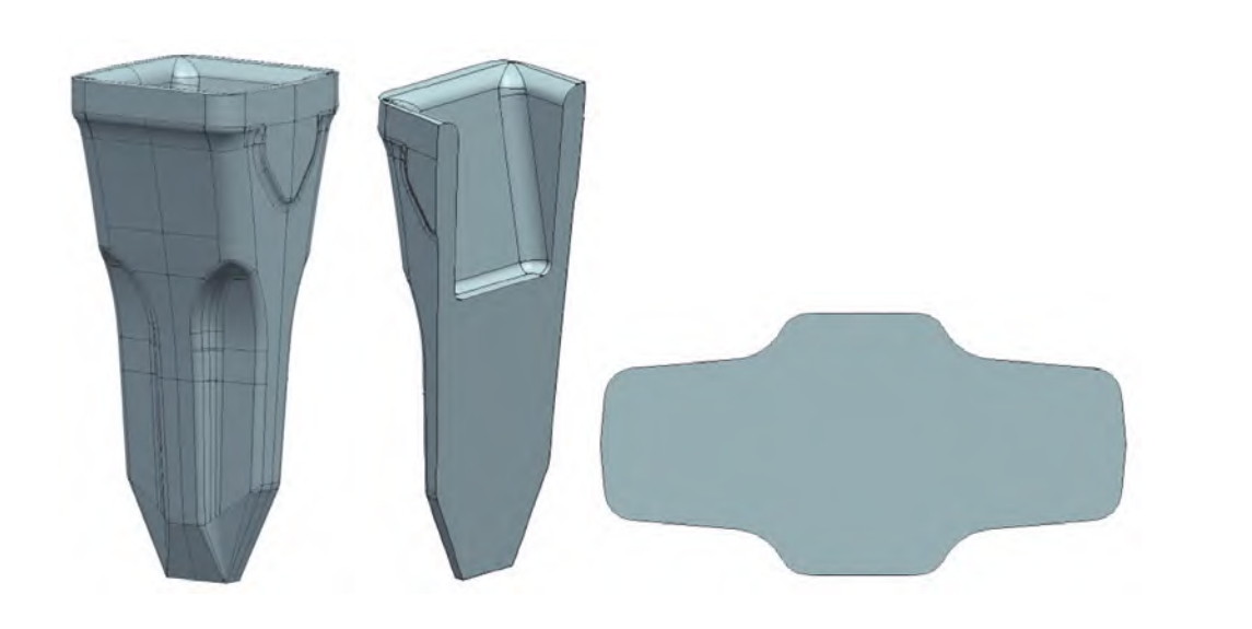
2.1 Product Structure and Forging Requirements
The bucket teeth studied in this article have a forging quality of 21.5kg and are made of 42CrMo. The overall cross-section of the bucket teeth changes significantly, with a large cross-section at the pin seat position and a very small cross-section at the tooth tip. The pin seat hole needs to be forged, so the workpiece must be produced in a vertical forging manner. Due to the small cross-sectional area at the tooth tip, it is difficult for the metal to flow to the sharp corner during forging. Therefore, it is necessary to reserve the metal blank required for the sharp corner during preform making.
2.2 Selection of Equipment and Initial Design of Blank
Given the characteristics of the bucket teeth, a φ560mm automatic roll forging machine is selected for preform making, and a 2500t electric screw press is used for final forging. Considering the shape of the bucket teeth and the requirements of the forging process, the original bar diameter is selected as . The schematic diagram of the initial roll forging blank is designed as shown in Figure 2. However, due to the high height-diameter ratio and the tapered structure at the bottom, a heading process is added before final forging to ensure the stability of the blank during final forging and the smooth flow of the metal into the cavity.
3. Design of Roll Forging Die
3.1 Selection of Roll Forging Passes
Although the overall cross-section of the bucket teeth changes significantly, the most significant change occurs at the tip. The cross-section in the middle and upper parts is relatively stable and is in a cross shape. By calculating the total elongation coefficient according to the minimum cross-section area, and considering that the average elongation coefficient is 1.6, the calculated roll forging passes are 1.82, which is rounded up to 2. However, due to the high elongation coefficient of the small head and the single-head variable cross-section elongation characteristics, as well as the cross-shaped cross-section of the roll forging part, an additional shaping pass is required after two passes of preform roll forging, resulting in a total of three passes of roll forging for preform making.
3.2 Determination of Roll Forging Groove System
To improve the efficiency of elongation and ensure the quality of the preform, the oval – circular groove system is improved to an oval – elliptical groove system. The cross-sectional sizes of the first, second, and third passes of the groove system are determined by reverse calculation based on the principle of equal volume and are shown in Figures 4, 5, and 6 respectively.
3.3 Design of Roll Forging Mold
According to the shape of the roll forging part, the roll forging mold for each pass is designed. The mold cavity size is relatively simple, and the blank cross-section size is converted to the corresponding roll forging mold fan-shaped surface. Considering the characteristics of the preform making process, appropriate front slip coefficients are considered. The characteristic groove types of this design are oval and cross-shaped, which are evenly transitioned along the ridge line on the fan-shaped mold. A material receiving bin is set at the end of the roll forging mold to reduce the occurrence of flash caused by inaccurate blanking size. The roll forging torques for the first, second, and third passes are 80kNm, 42kNm, and 18kNm respectively, which meet the requirements of the selected automatic roll forging machine.
4. Finite Element Numerical Simulation of Bucket Teeth Precision Roll Forging – Integral Die Forging
4.1 Precision Roll Forging Numerical Simulation
The geometric model established above is imported into the finite element numerical simulation software. The rotation and speed constraints of the roll forging mold are set according to the actual speed of the roll forging machine. At the same time, the blank is imported into the software, and the blank, mold temperature, and material are set, and the grid is divided, and the corresponding boundary conditions are set to establish a finite element numerical model as shown in Figure 8. After each pass of roll forging, the blank is rotated 90 degrees and placed in the next mold for roll forging. The simulation results of each pass of roll forging are shown in Figure 9. It can be seen that the cross-sectional shape of the third pass of roll forging basically meets the design requirements, the blank is reasonably distributed, and no flash, scraping, or instability phenomena occur. However, due to the non-fully enclosed cavity during the roll forging process, the final shape cannot completely match the roll forging cavity size.
4.2 Integral Die Forging Numerical Simulation
The numerical model of the roll forging is exported and placed in the heading and final forging molds to establish a heading, final forging finite element numerical model as shown in Figure 10. It can be seen that the shape of the roll forging part basically meets the design requirements and can be smoothly placed in the heading and final forging cavities, further verifying the feasibility of the roll forging design. The heading and final forging forming effects are shown in Figure 11. The heading pressure is small, only 221t, and the metal at the bottom of the blank hardly flows during heading, and the metal flow occurs at the large head. The final forging forming load is 2750t, and the selected 2500t electric screw press can meet the requirements. The cavity is completely filled during final forging, the material utilization rate is as high as 92%, and no folding, scraping, or other defects occur, and the flash is small and evenly distributed, further verifying the feasibility of the process design.
5. Summary and Conclusion
5.1 Summary of the Process
The following table summarizes the key steps and parameters of the precision roll forging – integral die forging process for bucket teeth:
| Process Step | Equipment | Parameters |
|---|---|---|
| Roll Forging Preform | φ560mm automatic roll forging machine | 3 passes of roll forging, oval – elliptical groove system, first pass torque: 80kNm, second pass torque: 42kNm, third pass torque: 18kNm |
| Heading | – | Before final forging, heading process to ensure blank stability |
| Final Forging | 2500t electric screw press | Final forging load: 2750t, material utilization rate: 92% |
5.2 Conclusion
Through the structural analysis of bucket teeth, a precision roll forging – integral die forging forming process has been proposed, and relevant process designs have been carried out. The material utilization rate is 92%, and the bucket teeth can be successfully formed on the existing φ560mm automatic roll forging machine and 2500t electric screw press. This process provides a new design idea for the same type of bucket teeth and has certain reference significance for the casting-to-forging process transformation of bucket teeth. Future research can focus on further optimizing the process parameters to improve the quality and performance of bucket teeth.