
Throughout my career in foundry engineering, I have dedicated significant effort to addressing the pervasive issue of slag inclusions in ductile iron castings, particularly for critical components like crankshafts. Slag inclusions, those detrimental non-metallic particles entrapped within the casting matrix, are a primary source of rejection in high-integrity applications. This article synthesizes my practical experiences and theoretical explorations into a comprehensive guide on eliminating these defects. The focus is on crankshafts for machinery, where the demand for flawless, machined surfaces is paramount. The battle against slag inclusions is multifaceted, involving molten metal treatment, gating system design, pouring practices, and solidification control. I will delve into each aspect, supported by data, models, and comparative analyses, to provide a holistic understanding of how to achieve consistent, slag-free ductile iron castings.
The detrimental impact of slag inclusions cannot be overstated. These defects manifest as dark, non-lustrous spots or streaks on machined surfaces, often leading to catastrophic failure under cyclic loading. In applications like crankshafts, where magnetic particle inspection reveals even the most minute flaw, the presence of slag inclusions translates directly into high scrap rates and disrupted production schedules. My journey began with a process that, despite conventional slag-control measures, yielded an unacceptably high scrap rate due to these inclusions. The quest for a solution led to a fundamental redesign of the casting process, which successfully brought the defect rate to near zero. This narrative is not just about a single case; it is a framework for understanding the genesis of slag inclusions and implementing robust countermeasures.
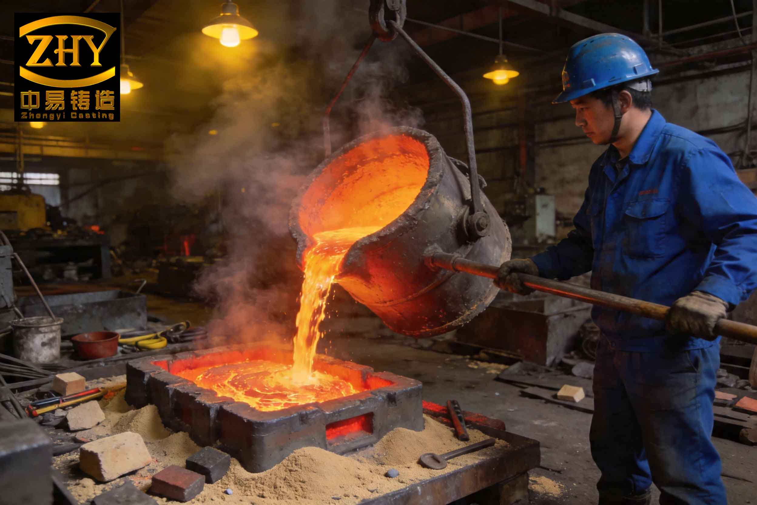
To understand how to prevent slag inclusions, one must first comprehend their nature and origin. Slag inclusions in ductile iron typically consist of oxides, sulfides, or other reaction products formed during melting, treatment, and pouring. They can be primary (carried over from the furnace or ladle) or secondary (formed within the mold cavity due to turbulence and oxidation). The following image illustrates the typical morphology of such defects on a cast surface, highlighting their irregular, often clustered appearance.
The formation of slag inclusions is governed by principles of fluid dynamics and thermodynamics. The tendency for a slag particle to separate from the molten iron depends on the density difference, the viscosity of the iron, and the flow conditions. A fundamental equation describing the terminal rising velocity of a spherical slag particle in a quiescent melt is given by Stokes’ law, modified for particles moving in a fluid medium:
$$ v_r = \frac{2 (\rho_{iron} – \rho_{slag}) g r^2}{9 \mu} $$
Here, \( v_r \) is the rising velocity (m/s), \( \rho_{iron} \) is the density of molten ductile iron (approximately 7000 kg/m³), \( \rho_{slag} \) is the density of the slag inclusion (typically 2500-3000 kg/m³), \( g \) is the acceleration due to gravity (9.81 m/s²), \( r \) is the radius of the slag particle (m), and \( \mu \) is the dynamic viscosity of the molten iron (Pa·s). This formula immediately reveals key leverage points: reducing slag particle size (\( r \)), increasing the temperature to lower viscosity (\( \mu \)), and ensuring sufficient time for flotation are all critical. For instance, a temperature increase from 1320°C to 1380°C can reduce viscosity by 15-20%, significantly enhancing slag floatation. The relationship between temperature (\( T \)) in Kelvin and viscosity can be approximated for iron melts by an Arrhenius-type equation:
$$ \mu = A \exp\left(\frac{E}{RT}\right) $$
where \( A \) is a pre-exponential factor, \( E \) is the activation energy for viscous flow, and \( R \) is the universal gas constant. This underscores the critical role of superheat in combating slag inclusions.
My initial process, which resulted in chronic slag inclusion problems, employed a horizontal molding and horizontal pouring (flat) approach. The gating system, while featuring a pouring basin, strainer core, and slag traps, was fundamentally flawed for this application. The analysis revealed several root causes for the persistent slag inclusions. The horizontal orientation meant the upper surface of the cavity had a large, flat area where molten metal coverage was slow and incomplete, creating stagnant zones where slag particles could easily settle and become entrapped instead of floating to a designed collection point. The pouring temperature was maintained at a relatively low range of 1300-1320°C. At this lower superheat, the fluidity is reduced, and the viscosity is higher, which hampers the ability of slag inclusions to float out. Furthermore, the surface oxide film (dross) that forms on the molten iron becomes more stable and prone to being torn and entrained during turbulent filling.
The gating system itself promoted turbulence. The layout was complex, with multiple right-angle turns and sudden expansions, converting the metal stream’s kinetic energy into chaotic eddies. This severe turbulence fragments any protective oxide skin and disperses slag particles throughout the cavity. A key metric for evaluating gating design is the Reynolds number (\( Re \)), which predicts flow regime:
$$ Re = \frac{\rho v D_h}{\mu} $$
where \( v \) is the flow velocity and \( D_h \) is the hydraulic diameter of the channel. A high \( Re \) (>2000 for channel flow) indicates turbulent flow, which is detrimental for clean metal entry. The original design likely operated in a highly turbulent regime. Additionally, the choke (smallest cross-sectional area) was placed after the main runner, creating an unpressurized, open system with a high gating ratio (e.g., ΣA_sprue : ΣA_runner : ΣA_ingate = 1 : 2 : 2). This allowed the initial, cooler, and dirtier metal from the ladle to rush into the cavity, while the risers, placed conventionally, were ineffective in trapping this initial contaminated flow. The following table contrasts the critical parameters of the problematic original process with the principles of an improved one.
| Process Feature | Original Process (Prone to Slag Inclusions) | Improved Process Principles (Slag Inclusion Prevention) |
|---|---|---|
| Molding & Pouring Orientation | Horizontal mold, horizontal pour (flat). | Horizontal mold, vertical pour (tilted or vertical gating). |
| Pouring Temperature | 1300 – 1320°C (Lower superheat). | 1360 – 1380°C (Higher superheat). |
| Gating System Flow Character | Complex, turbulent, unpressurized (open). | Simplified, laminar, pressurized (choke at base). |
| Slag Trapping Mechanism | Passive: reliance on strainer and traps in runners. | Active: use of pouring basin dam, swirl gates, and blind risers as slag collectors. |
| Metal Entry into Cavity | Direct, high-velocity entry promoting splashing. | Bottom or stepped gating with tapered sprue for smooth, progressive filling. |
| Riser Function | Primarily for feeding, ineffective for slag collection. | Dual function: feeding and as a hot, quiet slag collection reservoir. |
| Initial Metal Quality | First metal enters cavity directly. | Initial cold/dirty metal diverted to a dump basin or blind runner. |
The redesigned process that successfully eliminated slag inclusions incorporated several synergistic changes. The most significant shift was from a horizontal pour to a vertical pour within a horizontally parted mold. This immediately changed the geometry of the cavity filling. The metal now rises steadily from the bottom, pushing air and any early-entrained slag inclusions upward ahead of the solidifying front. The top of the casting is the last to fill, and it is crowned with a sizable blind riser. This riser serves a dual purpose: it provides feed metal for solidification shrinkage and, more importantly, acts as a designated slag collection basin. The hot metal residing in the riser remains liquid longest, allowing ample time for any remaining slag inclusions to float into it and be sequestered away from the casting body.
The gating system was radically simplified and engineered for laminar flow. A tapered sprue was used to maintain a choked, pressurized flow from the very beginning, preventing aspiration and controlling velocity. The system employed a stepped or multi-level ingate design. The lowest ingates introduce metal at the base of the cavity to establish a calm, upward fill. The upper ingates open into the riser itself, delivering hot metal directly to this slag-collecting reservoir late in the pour, reinforcing its thermal efficiency and slag-holding capacity. A critical addition was an external slag-trapping device, such as a whirl gate or a dam in the pouring basin, coupled with a system to divert the initial ladle stream. This is often implemented using a stopper rod in a specially designed pouring cup or a launder with a dam. The first few kilograms of metal, which are coolest and carry the most slag from the ladle’s surface, are held back and prevented from entering the sprue. Only after this “dirty” metal is contained does the clean metal from the heart of the ladle flow into the mold. This principle can be modeled by considering the mass flow rate and the volume of the initial contaminated zone.
Let \( \dot{m} \) be the mass pouring rate, and \( V_{contaminated} \) be the estimated volume of metal in the ladle prone to carrying slag inclusions. The time \( t_{divert} \) for which the initial flow must be diverted is:
$$ t_{divert} = \frac{V_{contaminated} \cdot \rho_{iron}}{\dot{m}} $$
Ensuring the dumping basin has a volume \( V_{dump} \geq V_{contaminated} \) is crucial for effective slag inclusion prevention at the source.
Beyond the macroscopic process changes, the metallurgical aspects are vital. The treatment of ductile iron itself—nodulization and inoculation—generates reaction products that can become slag inclusions if not properly managed. Efficient post-inoculation slag skimming and the use of cover fluxes in the ladle are essential. The chemistry also plays a role. Elements like magnesium (from nodulization) and cerium increase the tendency to form stable, light oxides that can easily become dispersed slag inclusions. Controlling residual magnesium levels and using inoculants with anti-fading and slag-forming properties must be balanced. The following table outlines key metallurgical factors influencing slag inclusion formation.
| Factor | Effect on Slag Inclusions | Control Parameter / Optimal Range |
|---|---|---|
| Residual Magnesium (Mg) | High Mg increases oxide/sulfide slag formation. Creates a thicker, more tenacious dross. | 0.03% – 0.05% (Aim for the lower end of specification). |
| Pouring Temperature | Low temperature increases viscosity, reducing slag float-out. High temperature improves fluidity but may increase oxidation. | >1350°C for section sizes >25mm. Balance fluidity and oxidation. |
| Inoculation Practice | Late stream inoculation generates fewer inclusion-prone reaction products than ladle inoculation. | Prefer mold-injection or in-stream inoculation systems. |
| Slag Basicity | In ladle, a fluid, basic slag helps absorb inclusions. Acidic, viscous slag is less effective. | Use CaO-based covering fluxes to maintain basic slag with a basicity index >1.5. |
| Hold Time After Treatment | Insufficient holding leads to entrapment of treatment slag. Excessive holding leads to fading and temperature loss. | 3-8 minutes for slag agglomeration and flotation before pouring. |
The success of the improved process is not merely anecdotal; it can be quantified through quality metrics. After implementation, the scrap rate due to slag inclusions dropped from a persistent high level (often above 30% on critical machining stages) to virtually zero. Statistical process control charts showed a dramatic shift in the process mean for defect counts. This improvement is sustained over long production runs, validating the robustness of the design. The underlying physics can be further modeled by considering the solidification sequence. The use of a top riser as a hot spot ensures directional solidification towards it. The temperature gradient \( G \) and the solidification rate \( R \) govern the movement of the liquidus isotherm. For effective slag collection, the riser must remain liquid long after the casting surface has solidified. The solidification time \( t_s \) of a section can be approximated by Chvorinov’s rule:
$$ t_s = B \cdot \left( \frac{V}{A} \right)^n $$
where \( V \) is volume, \( A \) is surface area, \( B \) is a mold constant, and \( n \) is an exponent (typically ~2). Designing the riser with a higher modulus \( (V/A)_{riser} \) than the casting modulus \( (V/A)_{casting} \) ensures it solidifies last. In our case, the riser’s modulus was calculated to be at least 1.2 times that of the heaviest section of the crankshaft. This prolonged liquid state provides the necessary time (\( \Delta t \)) for slag particles to float from the casting into the riser. Combining this with Stokes’ law, we can estimate the maximum depth \( h \) in the casting from which a slag particle of radius \( r \) can still reach the riser:
$$ h = v_r \cdot \Delta t = \frac{2 (\rho_{iron} – \rho_{slag}) g r^2}{9 \mu} \cdot \left( t_{s,riser} – t_{s,casting\_section} \right) $$
This equation powerfully illustrates the interplay between particle size, metal fluidity (via \( \mu \)), and solidification design in determining the effectiveness of the riser as a slag inclusion sink.
The application of these principles extends beyond a single crankshaft design. I have successfully adapted this methodology to other similarly challenging castings, such as different crankshafts for various engines and other thick-section, high-integrity ductile iron components. The core philosophy remains constant: control the metal quality before it enters the mold, guide it into the cavity with minimal turbulence, and provide a designed, hot, and quiet location for any residual slag inclusions to collect. This requires a systemic view, where pouring practice, gating geometry, riser design, and metallurgical control are optimized in concert.
In conclusion, the prevention of slag inclusions in ductile iron crankshafts is an achievable goal through disciplined engineering of the entire casting process. It requires abandoning traditional but flawed practices like flat pouring for certain geometries and embracing concepts that prioritize clean, quiescent metal entry and proactive slag collection. The key takeaways from my experience are unequivocal: elevate pouring temperatures to enhance fluidity and slag floatation; redesign gating for pressurized, laminar flow; employ vertical or stepped filling to facilitate the natural upward movement of slag inclusions; and utilize risers not just as feeders but as integral parts of the slag management system. The mathematical models governing particle flotation, fluid flow, and solidification provide a solid theoretical foundation for these practical steps. By relentlessly focusing on excluding slag at every stage—from ladle treatment to mold filling—foundries can consistently produce high-integrity ductile iron castings free from the scourge of slag inclusions, ensuring reliability, reducing costs, and meeting the most stringent quality standards.